Assembly Procedure
Assembly Procedure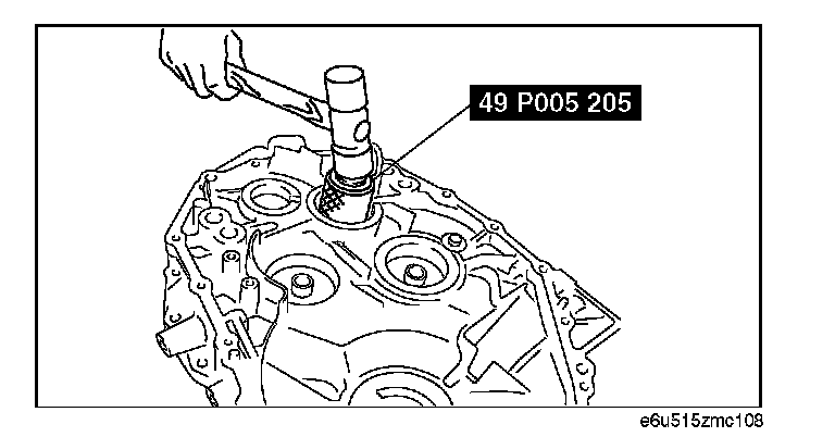
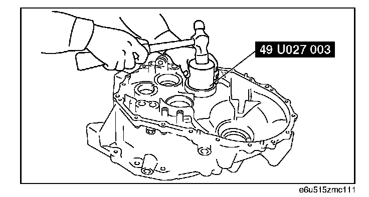
1. Install a new primary shaft oil seal in the clutch housing using the SST.
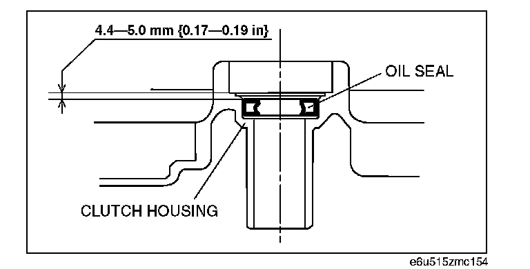
Oil seal press-in depth:
4.4 - 5.0 mm (0.17 - 0.19 in)
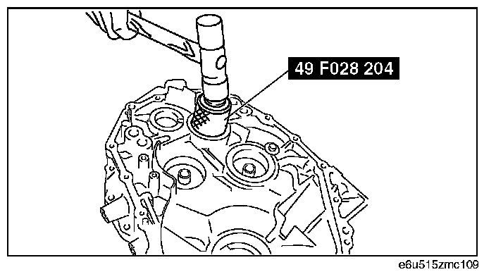
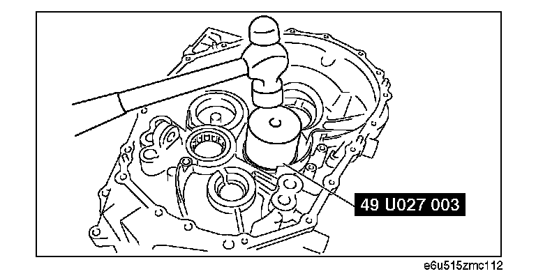
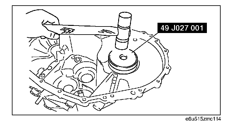
2. Install a new primary shaft front bearing using the SST.
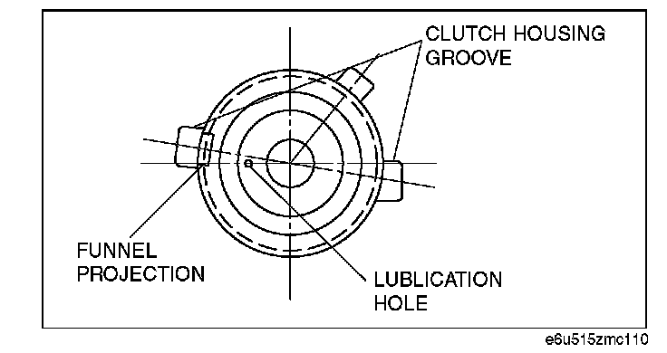
3. Install the oil funnel for in the secondary shaft (No.1 and No.2) to the clutch housing.
Note:
^ Align the clutch housing groove and the funnel projection, and insert.
^ Lubrication hole can be positioned either on the left or right.
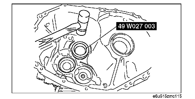
4. Install a new secondary shaft (No.1) front bearing using the SST.
5. Install the secondary shaft (No.2) front bearing outer race using the SST.
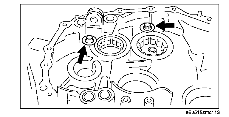
6. Install the primary shaft bearing cover and secondary shaft (No.1) bearing cover.
Tightening torque:
6.8 - 15.8 N-m (69.4 - 161 kgf-cm, 60.2 - 139 in-lbf)
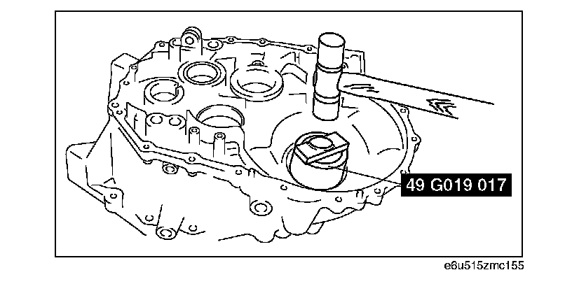
7. Install the differential side bearing outer race to the clutch housing using the SST.
8. Install the differential side bearing outer race and adjust shim to the transaxle case using the SST.
Note: Use the adjust shim selected in the differential side bearing preload adjustment. (See DIFFERENTIAL SIDE BEARING PRELOAD ADJUSTMENT.)
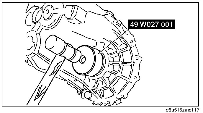
9. Install a new differential oil seal to the clutch housing using the SST.
2WD
AWD

10. Install the secondary shaft (No. 2) rear bearing outer race and adjust shim to the transaxle case using the SST.
Note: Use the adjust shim selected in the secondary shaft (No. 2) bearing preload adjustment. (See SECONDARY SHAFT (NO.2) BEARING PRELOAD ADJUSTMENT.)
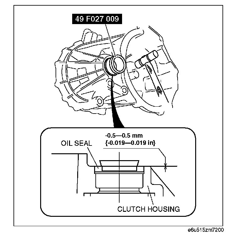
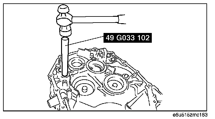
11. Install a new differential oil seal to the transaxle case using the SST.
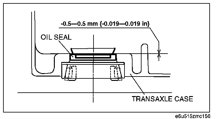
Oil seal press-in depth:
-0.5 - 0.5 mm (-0.019 - 0.019 in)
12. Install the new control rod bearings to the clutch housing and transaxle case using the SST.
Note: Assembling direction can be either way.
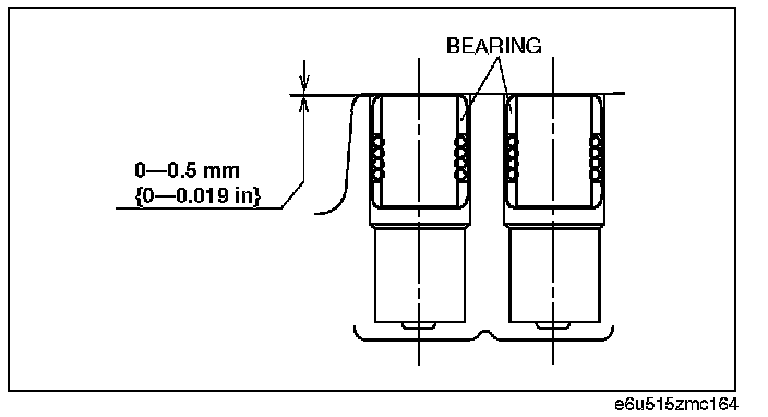
Bearing press-in depth:
0 - 0.5 mm (0 - 0.019 in)
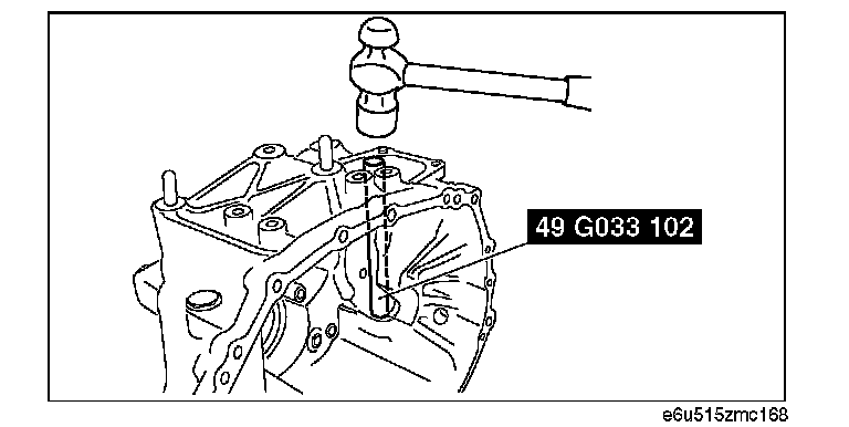
13. Install a new shift lever shaft bearing to the transaxle case using the SST.
Note: Assembling direction can be either way.
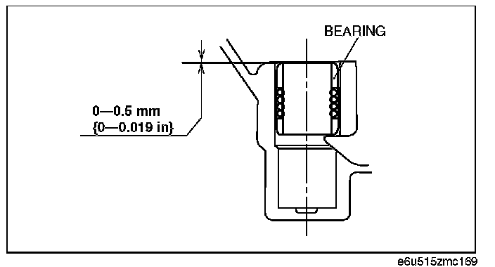
Bearing press-in depth:
0 - 0.5 mm (0 - 0.019 in)
14. Install the snap rings to the transaxle case.
15. Install each gear component.
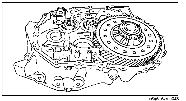
1) Install the differential to the clutch housing.
Caution: Installing the primary shaft can damage the oil seal, reducing the performance of the transaxle. When installing the primary shaft to the clutch housing, be careful not to damage it.
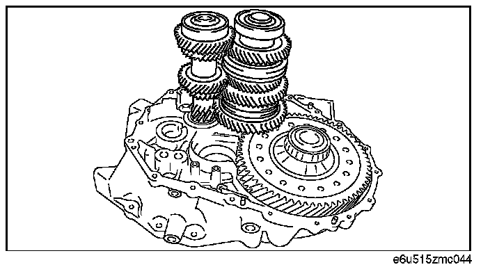
2) Install the primary shaft component and secondary shaft (No.1) component to the clutch housing at the same time.
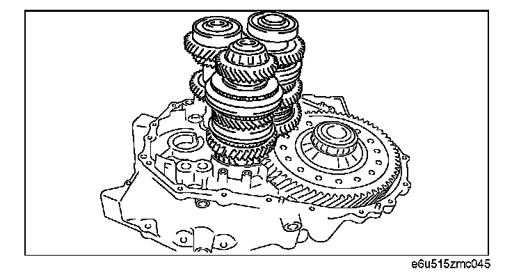
3) Install the secondary shaft (No.2) component.
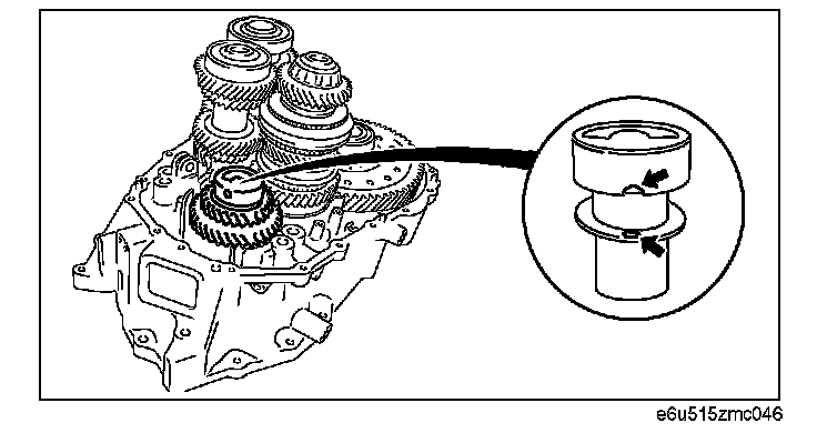
4) Install the reverse idler gear, needle bearing, thrust washer, and reverse idler gear shaft.
Caution:
^ Align the thrust washer rotation lock projection and reverse idle gear shaft groove.
^ Position the shaft direction as shown in the figure for the transaxle case assembly.
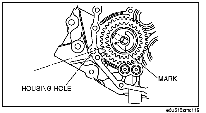
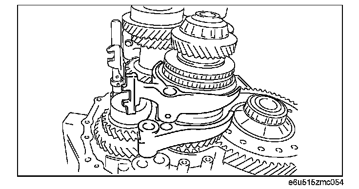
16. Install the 1st/2nd shift fork.
17. Install the counter lever and 3rd/4th control rod (A).
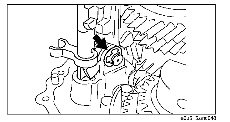
18. Install the counter lever pivot and secure it with the snap ring.
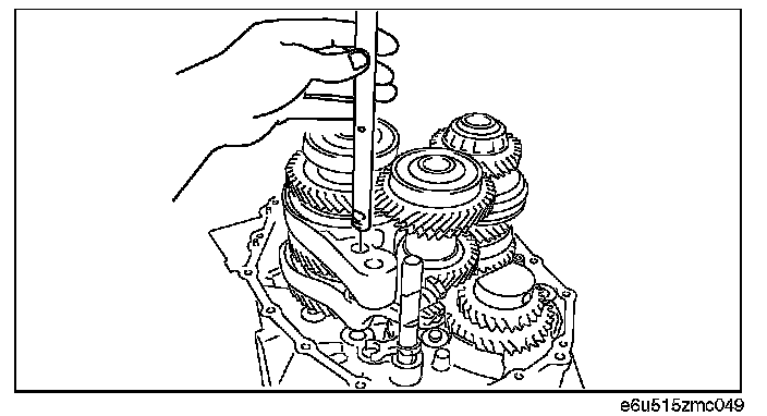
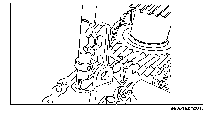
19. Install the 3rd/4th shift fork and then install the 1st/2nd control rod ball groove in the direction shown in the figure.
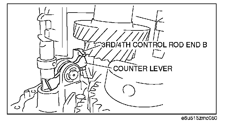
20. Install 3rd/4th control rod end (B) so that it engages with the counter lever as shown in the figure.
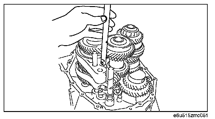
21. Install the 3rd/4th control rod (B) ball groove in the direction shown in the figure.

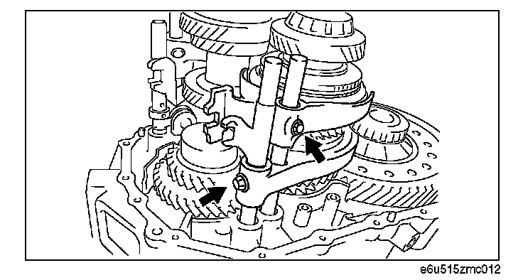
22. Tap in 3rd/4th control rod end (A and B) new spring pins shown in the figure.
23. Tap in 3rd/4th shift fork spring pin using a pin punch.
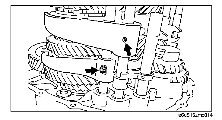
24. Install the 1st/2nd shift fork retaining bolt.
Tightening torque:
15.7 - 23.5 N-m (1.7 - 2.3 kgf-m, 11.6 - 17.3 ft-lbf)
25. Install the 5th/6th shift fork and reverse shift fork.
26. Install the 5th/6th control rod and reverse control rod being careful of the ball groove direction.
27. Install the reverse shift fork retaining bolt and 5th/6th shift fork retaining bolt.
Tightening torque:
15.7 - 23.5 N-m (1.7 - 2.3 kgf-m, 11.6 - 17.3 ft-lbf)
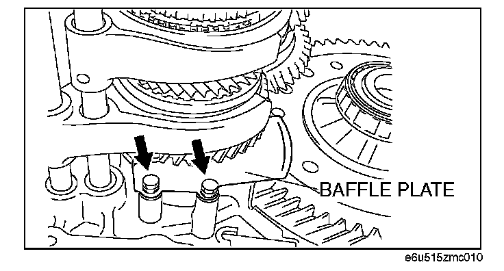
28. Install the baffle plate.
Tightening torque:
6.0 - 11.0 N-m (61.2 - 112.1 kgf-cm, 53.2 - 97.3 in-lbf)

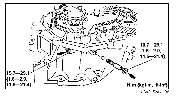
29. Install the detent ball, detent spring, detent spring seat, and sealing cap to the clutch housing.
30. Install the magnet to the clutch housing.
31. Install the oil pass to the transaxle case.
32. Install the transaxle case.

1) Apply a light coat of silicone sealant to the contact surfaces of the transaxle case and the clutch housing.
2) Place the transaxle case on the clutch housing.
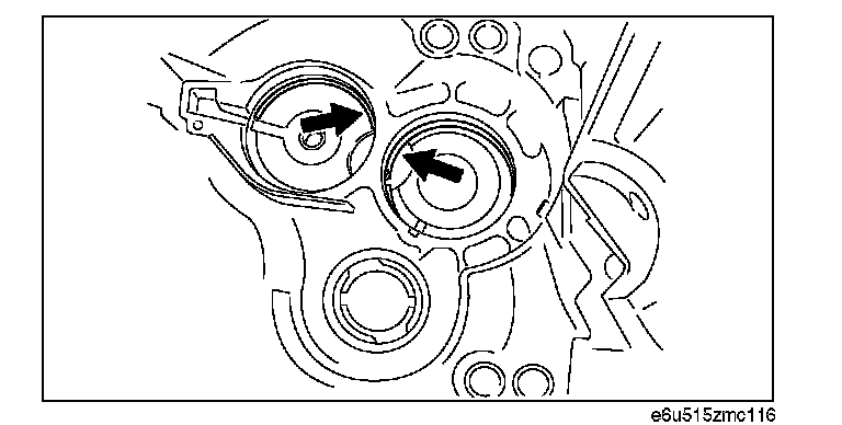
3) Install the bolt (M8 x 1.25) to the secondary shaft (No. 1) through the sealing cap hole.
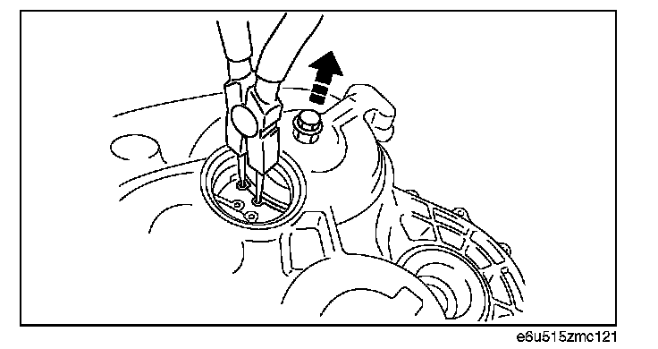
4) While pulling up the secondary shaft (No. 1) installation bolt, widen the snap ring, and then fix the snap ring into the secondary shaft bearing groove as shown in the figure.
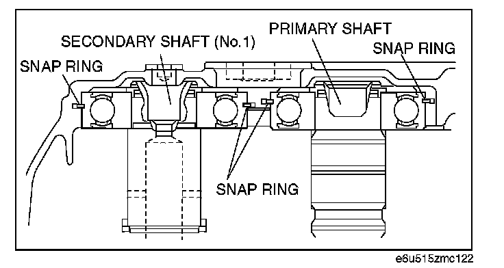
5) While pushing up the primary shaft from the clutch housing side, widen the snap ring (primary shaft side) and fix it into the primary shaft bearing groove.
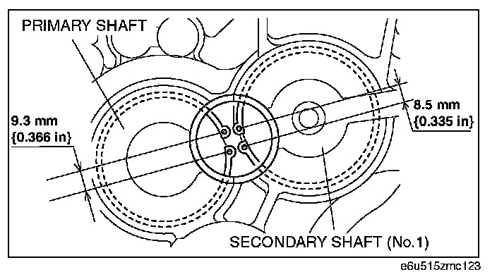
6) Measure the center-to-center distance of the respective snap ring holes as shown in the figure and verify that the snap ring is properly installed in the bearing groove.
7) Install the bolts to the transaxle case and clutch housing as shown in the figure.
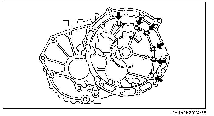
Front side fixing bolts
Tightening torque:
23.6 - 35.2 N-m (2.5 - 3.5 kgf-m, 17.5 - 25.9 ft-lbf)
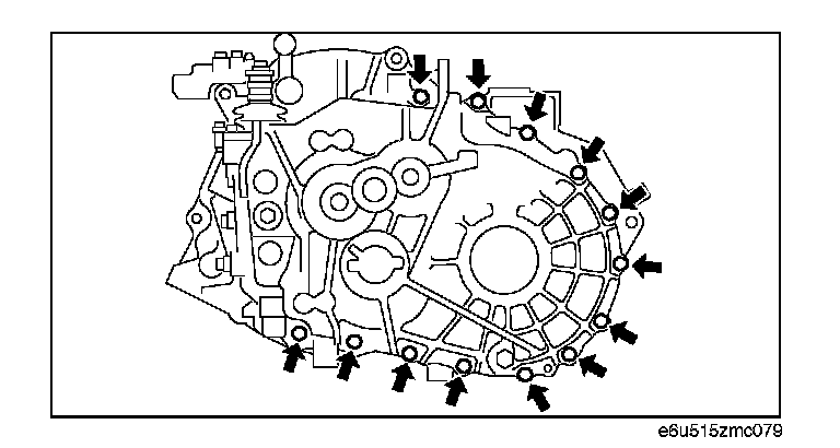
Rear side fixing bolts
Tightening torque:
23.6 - 35.2 N-m (2.5 - 3.5 kgf-m, 17.5 - 25.9 ft-lbf)
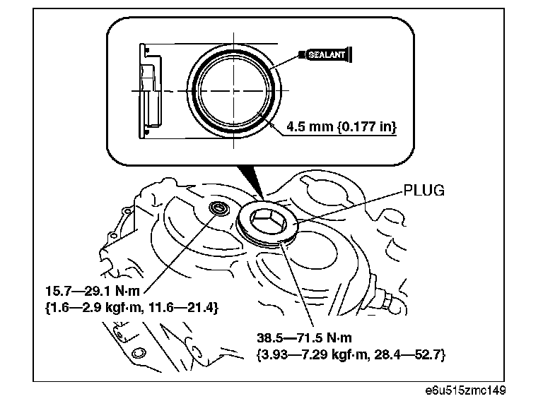
33. Install the new sealing caps.
Note: The cast hexagon inner diameter of the plug is 27mm (1.063 in).
34. Install the reverse idler shaft retaining bolt with new packing.
Tightening torque:
69.6 - 90.4 N-m (7.1 - 9.2 kgf-m, 51.4 - 66.6 ft-lbf)
35. Apply a coat of silicone sealant to the contact surface of the shift control case and the transaxle case.
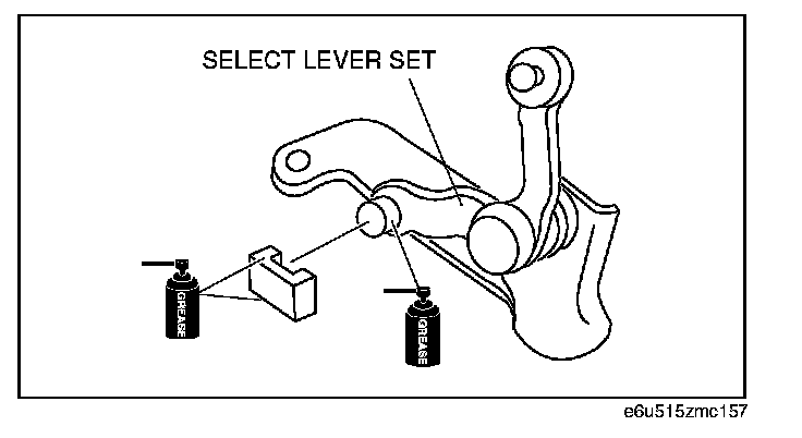
36. Install the select lever set and the shift component to the transaxle case.
Caution: Apply grease to the positions shown in the figure.

Caution: Be aware that the stem lengths of bolt A and B shown in the figure are different.
Tightening torque:
14.9 - 22.3 N-m (1.6 - 2.2 kgf-m, 11.0 - 16.4 ft-lbf)
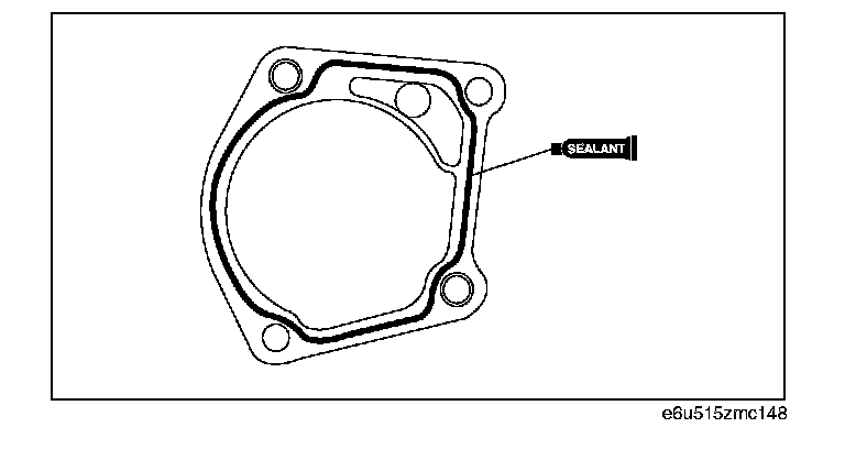
37. Install the neutral switch and back-up light switch with new packing.
Tightening torque:
28.2 - 52.2 N-m (2.9 - 5.3 kgf-m, 20.8 - 38.5 ft-lbf)

38. Install a new straight pin.
Tightening torque:
21.0 - 39.0 N-m (2.2 - 3.9 kgf-m, 15.5 - 28.7 ft-lbf)
39. Install a new shift push pin.
Tightening torque:
20.6 - 38.2 N-m (2.1 - 3.8 kgf-m, 15.2 - 28.1 ft-lbf)
40. Install a new select push pin.
Tightening torque:
27.5 - 50.9 N-m (2.9 - 5.1 kgf-m, 20.3 - 37.5 ft-lbf)
41. Install new packing, a drain plug, and a oil level plug.
Tightening torque:
27.5 - 50.9 N-m (2.9 - 5.1 kgf-m, 20.3 - 37.5 ft-lbf)