Drive Gear Case Component Assembly Procedure
Drive Gear Case Component Assembly Procedure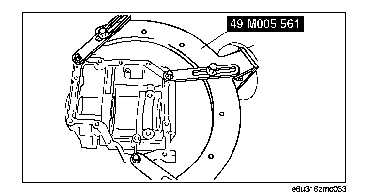
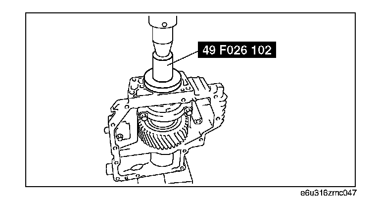
1. Install the drive gear case to the SST.
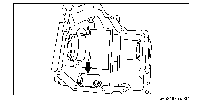
2. Install the baffle plate.
Tightening torque:
6.9 - 9.8 N-m (70 - 99 kgf-cm, 61 - 86 in-lbf)
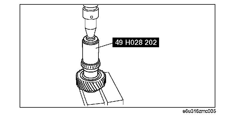
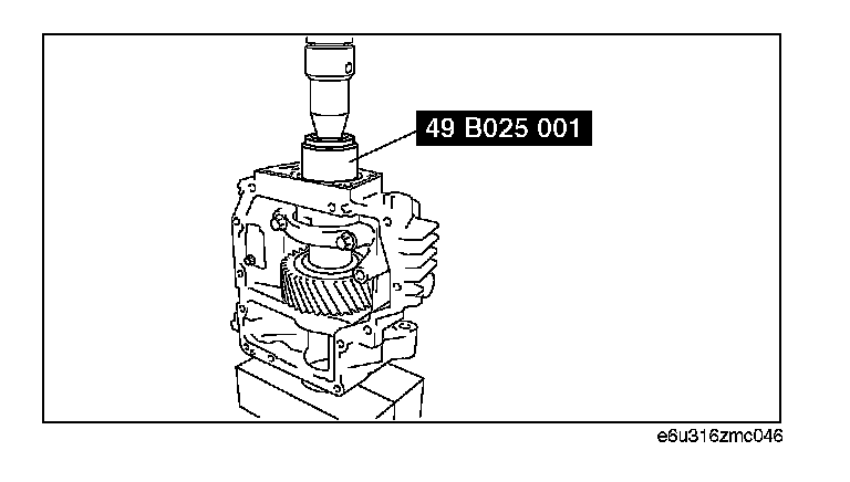
3. Using a press, assemble the bearing (RH).
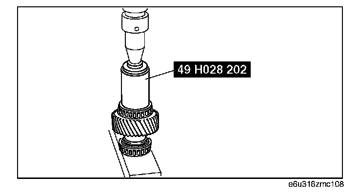
4. Using a press, assemble the bearing (LH).
5. Temporarily assemble the bearing outer race (RH) and spacer to the drive gear.
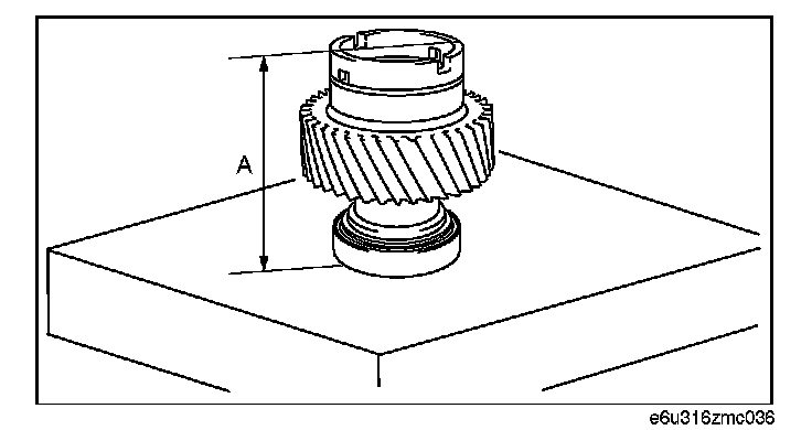
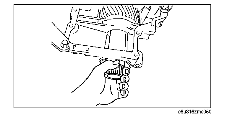
6. Place the drive gear component on the surface plate as shown in the figure, and measure the height using a vernier caliper or height gauge. This is dimension A.
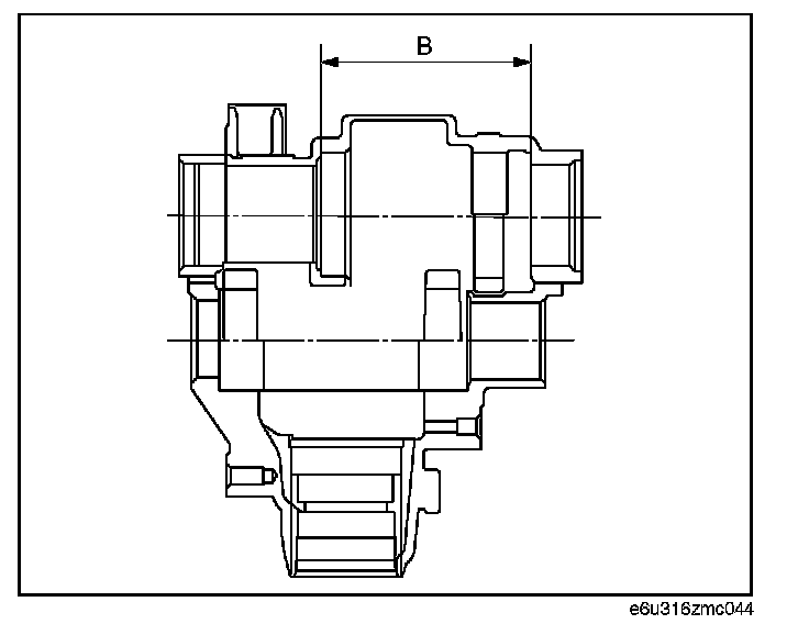
7. Measure the width of the drive gear installation area in the drive gear case. This is dimension B.
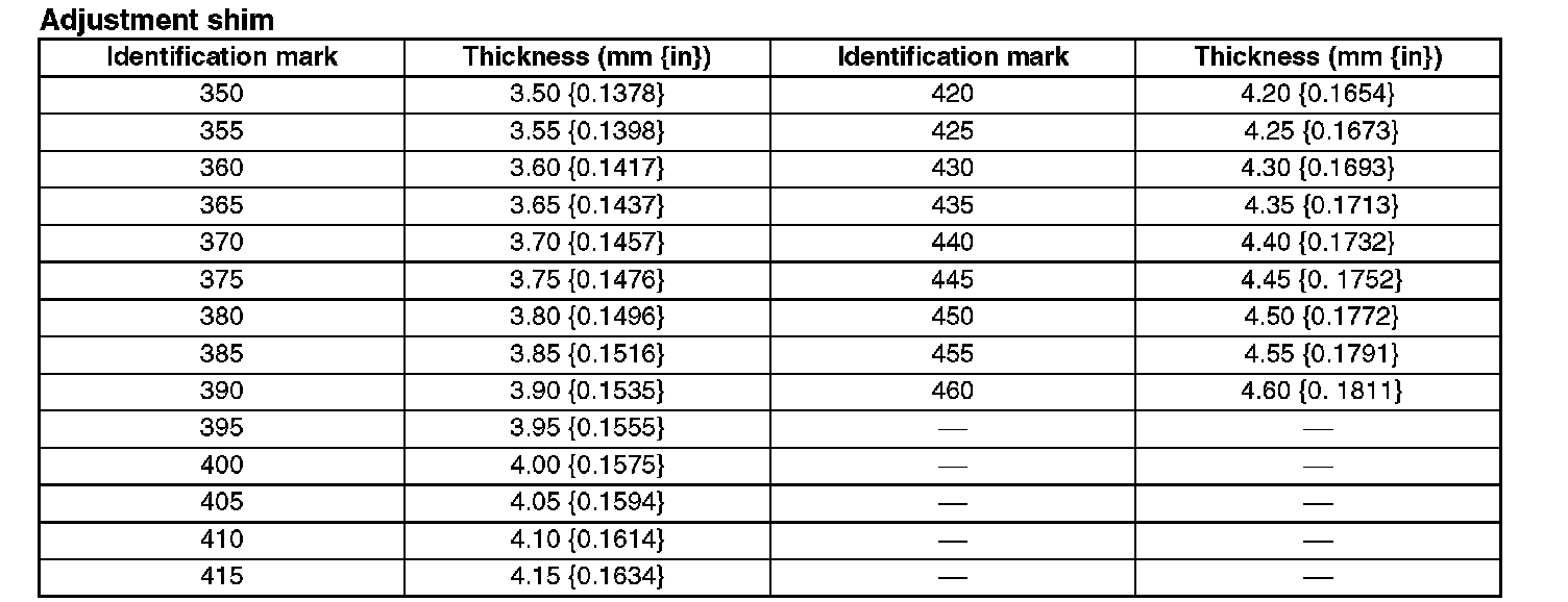
8. The maximum and minimum thickness C of the adjustment shim can be expressed by the following formula:
C = B - A - (0.01 - 0.03 mm (0.00039 - 0.00118 in))
9. If the thickness of the installed adjustment shim is within the C range, use the shim as it is.
10. If the thickness of the installed adjustment shim is not within the C range, select the appropriate adjustment shim from the table below and use it.
Adjustment shim
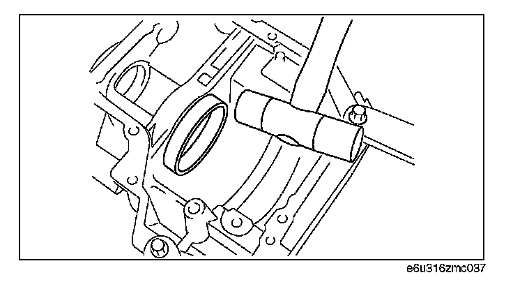
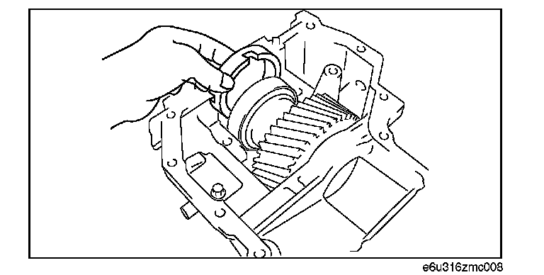
11. Using the plastic hammer, install the bearing outer race (LH).
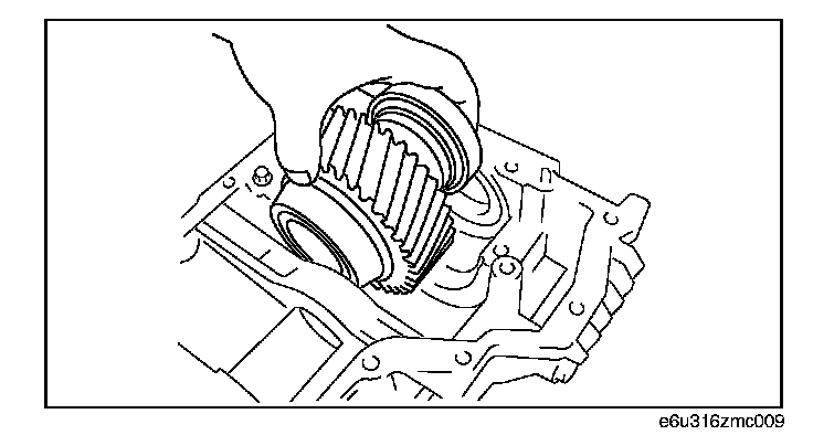
12. Install the drive gear component.
13. Install the spacer with its notch facing the bearing, and also facing upward, as shown in the figure.

14. Using a plastic hammer, assemble the adjustment shim.
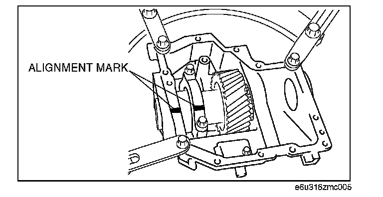
15. Align the bearing cap alignment marks, assemble the bearing cap.
Tightening torque:
37 - 51 N-m (3.8 - 5.2 kgf-m, 27.3 - 37.6 ft-lbf)
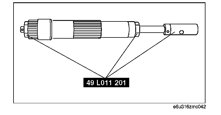
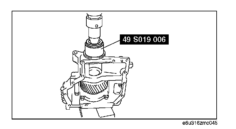
16. Assemble the SST to the drive gear shaft, and hand-tighten the nut.
SST tightening torque:
2.1 N-m (21 kgf-cm, 19 in-lbf)
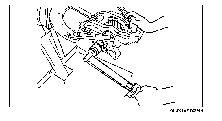
17. Install the drive gear shaft with the SST assembled and verify that the preload is within the specification using the torque wrench as shown in the figure.
Standard drive gear bearing preload:
0.6 - 2.1 N-m (6.2 - 21.4 kgf-cm, 5.4 - 18.5 in-lbf)
^ If the drive gear rotational torque is not within the specification, adjust it by selecting the proper spacer.
18. Remove the drive gear shaft.
19. Using a press, install the oil seals.
Note: Mark the press-in depth of each oil seal to the SST and press fit oil seals to the specified position.
Oil seal installation lengths
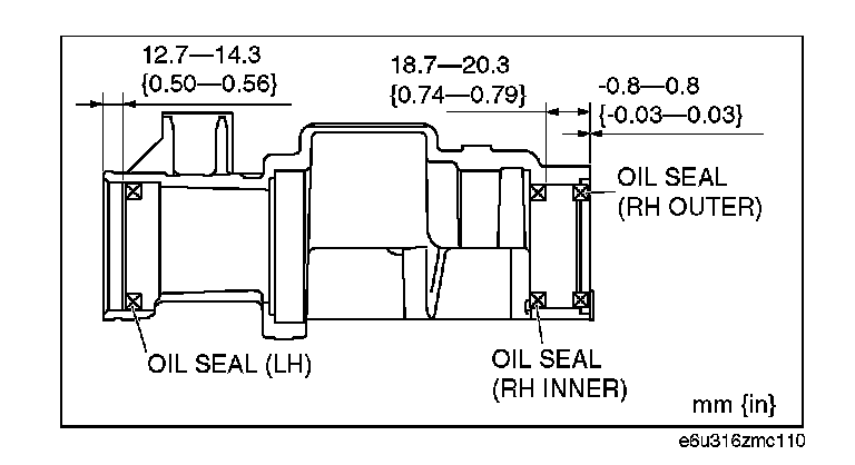
LH
RH inner
RH outer
20. Install the C-ring to the drive gear shaft and insert the drive gear shaft until it is secured by the C-ring.
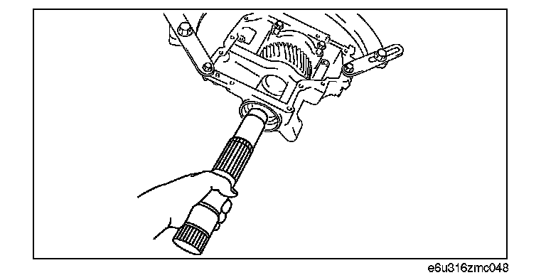
Caution: Be careful not to damage the oil seal when installing the drive gear shaft.
21. Pull the drive gear shaft by hand and verify that the drive gear shaft is secured by the C-ring at the specified position.