Valve Clearance: Adjustments
VALVE CLEARANCE ADJUSTMENT1. Disconnect the negative battery cable.
2. Remove the front tire (RH).
3. Remove the under cover.
4. Remove the splash shield (RH).
5. Remove the charge air cooler.
6. Remove the high pressure fuel pump.
7. Remove the ignition coils.
8. Disconnect the OCV connector.
9. Disconnect the CMP sensor connector.
10. Disconnect the P/S oil pump connector.
11. Remove the ventilation hose.
12. Remove the cylinder head cover.
13. Remove the drive belt.
14. Disconnect the front drive shaft (RH) from the joint shaft.
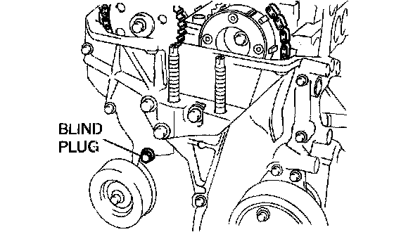
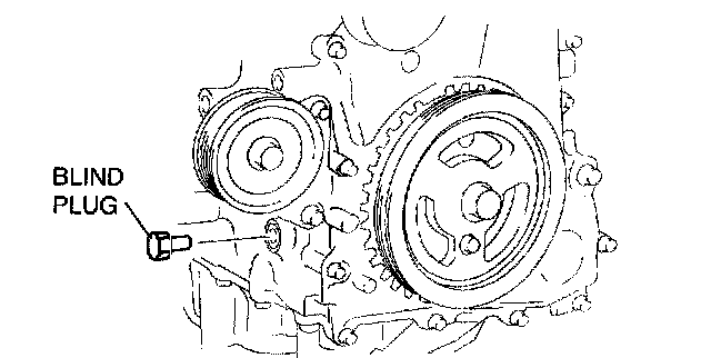
15. Remove the engine front cover lower blind plug.
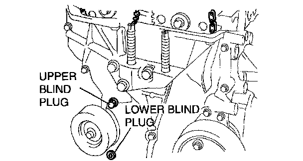
16. Remove the engine front cover upper blind plug.
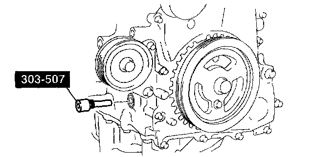
17. Remove the cylinder block lower blind plug, and install the SST.
18. Rotate the crankshaft clockwise so that the No.1 cylinder is at TDC of the compression stroke. (The position crank weight contacts the SST.)
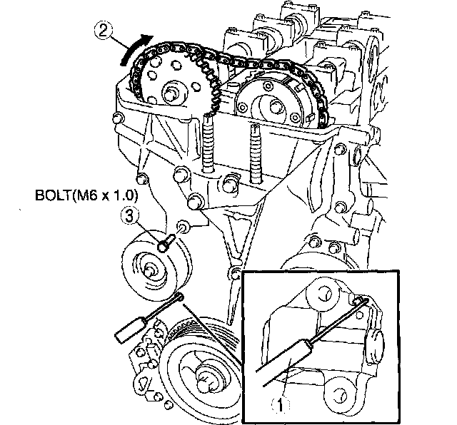
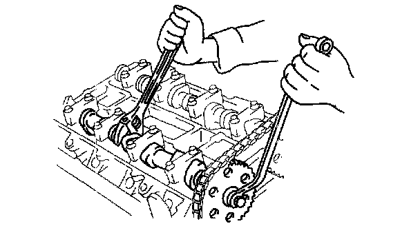
19. Release the tension on the timing chain.
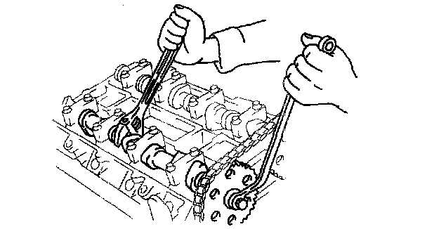
1) Using a suitable screwdriver or equivalent tool, unlock the chain tensioner ratchet.
2) Rotate the exhaust camshaft clockwise using a suitable wrench on the cast hexagon and loosen the tension on the timing chain.
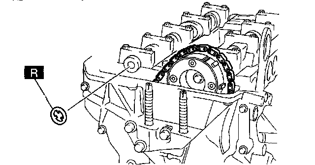
3) Using a suitable bolt (M6 X 1.0 length 25mm-35mm (0.99-1.37 inch)) at the engine front cover upper blind plug, secure the tensioner arm at the position where the tension is released.
20. Fix the exhaust camshaft using a wrench on the cast hexagon, and loosen the camshaft sprocket installation bolt.
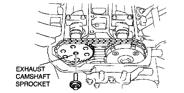
21. Remove the installation bolt and remove the exhaust camshaft sprocket.
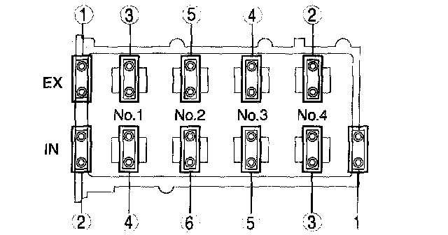
22. Loosen the camshaft cap bolts in two or three passes in the order shown in the figure and remove the camshaft cap.
Note:
- The camshaft caps are to be kept ordered for correct reassembly in their original positions. Do not mix the caps.
23. Remove the camshafts for the intake and exhaust sides.
24. Remove the tappet.
25. Install an appropriate tappet based on the results of the valve clearance inspection. Selected tappet = Removed tappet thickness + Measured valve clearance - Standard valve clearance
Standard valve clearance [Engine cold]
IN: 0.22 - 0.28 mm (0.0087 - 0.0110 inch)
EX: 0.27 - 0.33 mm (0.0107 - 0.0129 inch)
26. Install the camshaft with No.1 cylinder cam aligned at TDC of the compression stroke.
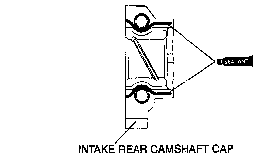
27. Carefully apply adhesive agent to the area indicated in the figure so that it does not leak into the sliding part.
Thickness 1.0 mm (0.039 inch)
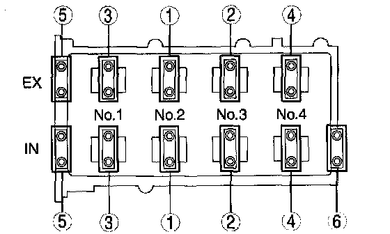
28. Install the camshaft caps and temporarily tighten the camshaft cap bolts evenly in two or three passes, and then tighten the camshaft cap bolts in two passes, using the following two steps and in the order shown in the figure.
Tightening procedure
(1) 5.0 - 9.0 Nm (51.0 - 91.7 kgf-cm, 44.3 - 79.6 inch lbs.)
(2) 14.0 - 17.0 Nm (1.5 - 1.7 kgf-m, 10.4 - 12.5 ft. lbs.)
29. Install a new washer.
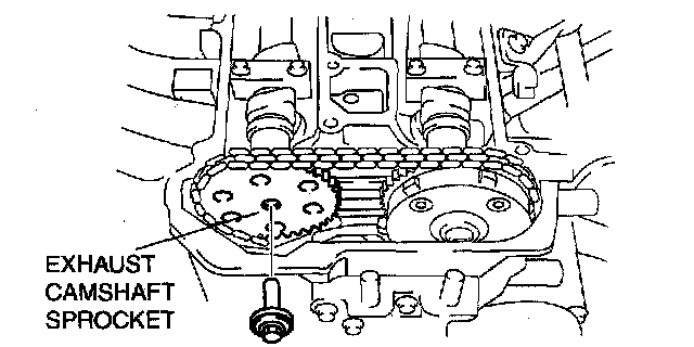
30. Install the exhaust camshaft sprocket.
Caution:
- Do not tighten the camshaft sprocket installation bolt at this stage. Verify the valve timing before performing the bolt tightening.
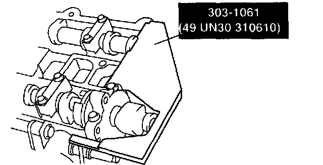
31. Install the SST on the camshaft as shown in the figure.
32. Remove the installation bolt for the engine front cover upper blind plug (M6 X 1.0 length 25 - 35 mm (0.99 - 1.37 inch)), and apply tension to the timing chain.
33. Rotate the crankshaft clockwise and verify that the No. 1 cylinder is at TDC of the compression stroke. (The position crank weight contacts the SST.)
34. Fix the exhaust camshaft using a wrench on the cast hexagon, and tighten the sprocket installation bolt.
Tightening torque 69 - 75 Nm (7.1 - 7.6 kgf-m, 50.9 - 55.3 ft. lbs.)
35. Remove the SST from the camshaft.
36. Remove the SST installed in the cylinder block lower blind plug hole.
37. Rotate the crankshaft clockwise two turns and inspect the valve timing.
- If it is not aligned, repeat the procedure.
38. Apply the silicone sealant and install the engine front cover upper blind plug.
Tightening torque 8.0 - 11.5 Nm (81.6 - 117.2 kgf-cm, 70.9 - 101.7 inch lbs.)
39. Install the cylinder block lower blind plug.
Tightening torque 18 - 22 Nm (1.9 - 2.2 kgf-m, 13.3 - 16.2 ft. lbs.)
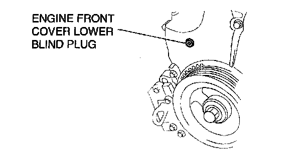
40. Install a new engine front cover lower blind plug.
Tightening torque 10.0 - 14.0 Nm (102.0 - 142.7 kgf-cm, 73.8 - 103.2 inch lbs.)
41. Connect the front drive shaft (RH) with the joint shaft.
42. Install the drive belt.
43. Install the cylinder head cover.
44. Install the ventilation hose.
45. Connect the P/S oil pump connector.
46. Connect the CMP sensor connector.
47. Connect the OCV connector.
48. Install the ignition coils.
49. Install the high pressure fuel pump.
50. Install the charge air cooler.
51. Install the splash shield (RH).
52. Install the under cover.
53. Install the front tire (RH).
54. Connect the negative battery cable.
55. Bleed the air from the cooling system.