Timing Chain: Service and Repair
TIMING CHAIN REMOVAL/INSTALLATION [L3 WITH TC]1. Disconnect the negative battery cable.
2. Remove the under cover.
3. Remove the front tire (RH).
4. Remove the splash shield (RH).
5. Remove the charge air cooler.
6. Remove the high pressure fuel pump.
7. Remove the ignition coils.
8. Disconnect the OCV connector.
9. Disconnect the CMP sensor connector.
10. Disconnect the P/S oil pump connector.
11. Remove the ventilation hose.
12. Remove the cylinder head cover.
13. Loosen the water pump pulley installation bolt and remove the drive belt.
14. Remove the CKP sensor.
15. Remove the P/S oil pump with the hoses and pipes still connected.
Note:
- Position and secure the P/S oil pump out of the way with a rope or wire.
16. Disconnect the front drive shaft (RH) from the joint shaft.

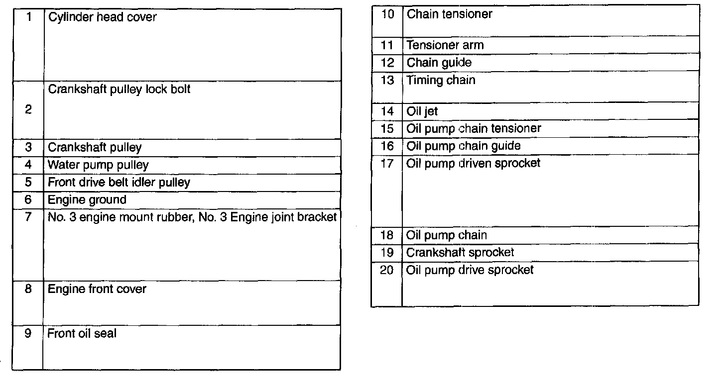
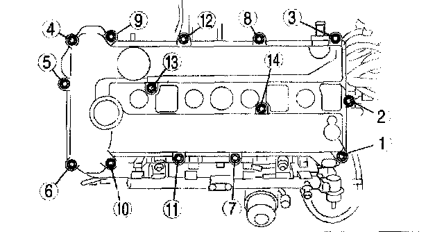
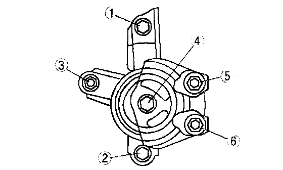
17. Remove in the order indicated in the figure.
18. Install in the reverse order of removal.
19. Start the engine and inspect and adjust the following:
1) Bleed the air from the cooling system.
2) Engine oil amount
3) Runout and contact of pulley and belt.
4) Ignition timing, idle speed, and idle mixture (CO and HC) verification.
20. Perform a road test and verify that there is no abnormal vibration or noise.
Cylinder Head Cover Removal Note
1. Loosen the cylinder head cover bolts in the order shown in the figure.
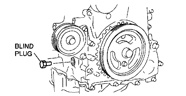
Crankshaft Pulley Lock Bolt Removal Note
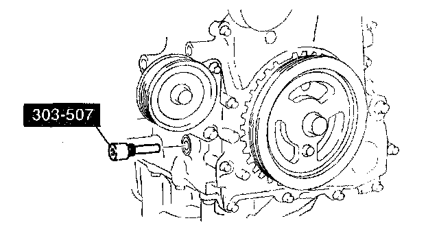
1. Remove the cylinder block lower blind plug and install the SST.
2. Rotate the crankshaft clockwise so that the No. 1 cylinder is at TDC of the compression stroke. (Position crank weight contacts SST.)
3. Install the SST to the crankshaft pulley and lock the crankshaft against rotation.
No.3 Engine Mount Rubber, No.3 Engine Joint Bracket Removal Note
1. Remove the air cleaner.
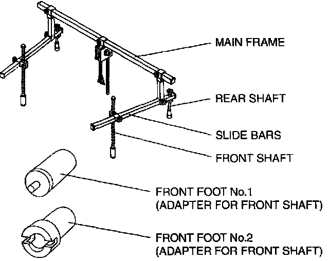
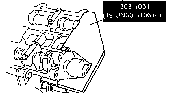
2. Install the SST using the following procedure.
Caution:
- Refer to the SST instruction manual for the basic handing procedure.
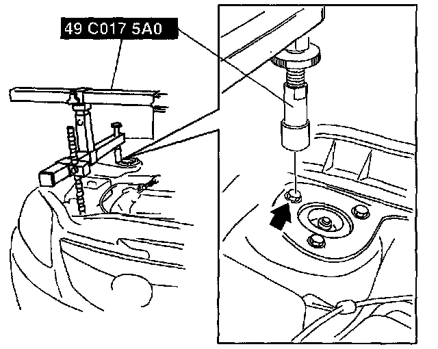
1) Install the right rear shaft of the SST to the bolt of the right shock absorber as shown in the figure.
2) Install the left rear shaft of the SST to the bolt of the left shock absorber. (Identical position to the right side)
Caution:
- When setting the SST on the right side, make sure it doesn't interfere with the DSC HU/CM.
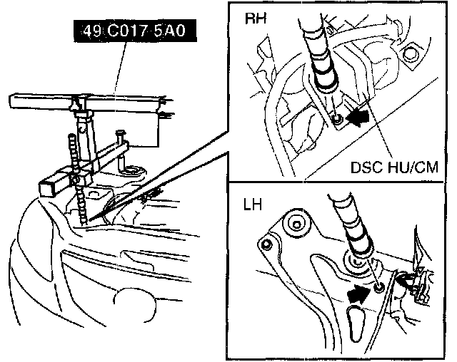
3) Install the left/right front shaft of the SST with front foot No.2 to the bolt as shown in the figure.
4) Adjust the positions of the SST side bars so that they are the same height (left and right) and horizontal.
5) Make sure each joint is securely tightened.
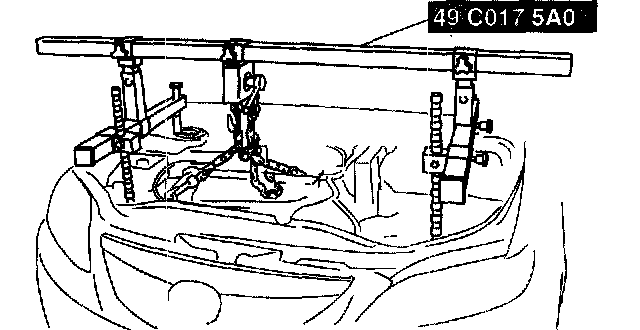
3. Support the engine using the SST.
Note:
- The SST (49 E017 5AO) can be used in place of the SST (49 C01 7 5AO).
Engine Front Cover Removal Note

1. Remove the front oil seal using a flathead screwdriver or similar tool.
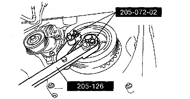
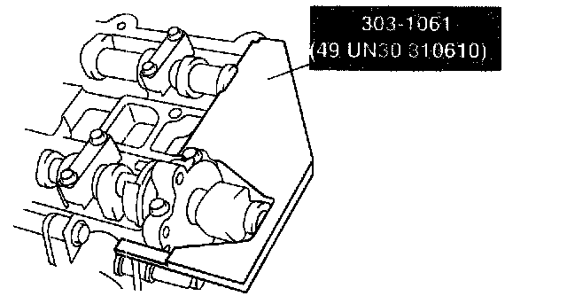
Chain Tensioner Removal Note
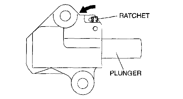
1. Press the timing chain tensioner ratchet to the left using a thin flathead screwdriver (precision screwdriver) to unlock the plunger.
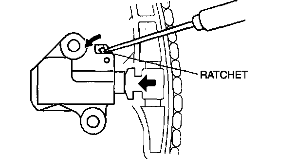
2. Slowly press the plunger back in the direction shown in the figure while pressing the ratchet.
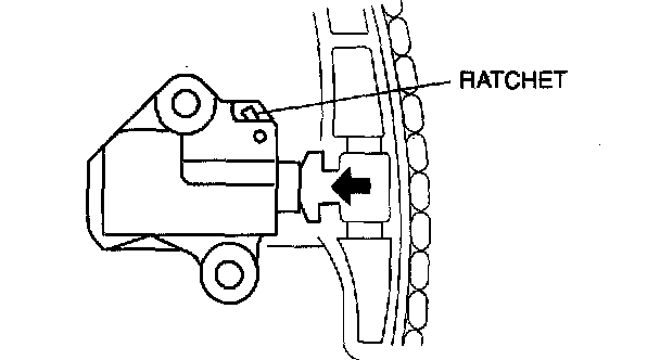
3. Release the ratchet with the plunger still pressed down.
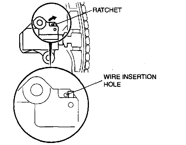
4. Press-in the plunger until the ratchet position is as indicated in the figure, and then insert the wire to lock the plunger.
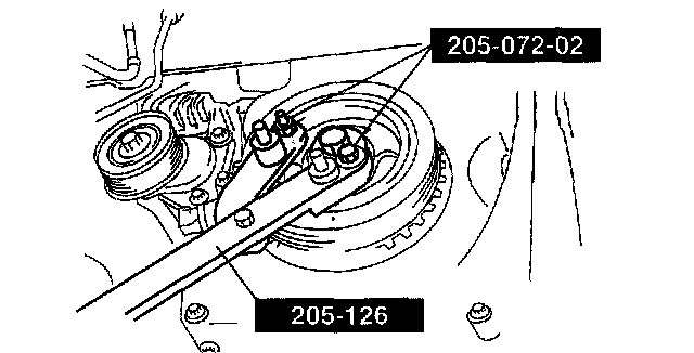
Oil Pump Driven Sprocket Removal Note
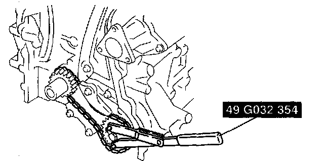
1. Install the SSTs to the oil pump driven sprocket, and lock it against rotation.
Oil Pump Drive Sprocket Installation Note
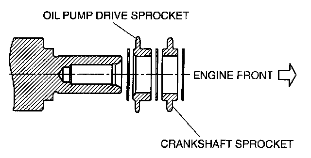
1. The oil pump drive sprocket has the assembly direction as shown in the figure.
Oil Pump Driven Sprocket Installation Note
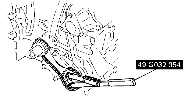
1. Install the SST to the oil pump driven sprocket and lock the oil pump against rotation.
Timing Chain Installation Note
1. Install the SST to the camshaft as shown in the figure.
2. Install the timing chain.
3. Remove the wire or paper clip from the chain tensioner piston and apply tension to the timing chain.
Front Oil Seal Installation Note
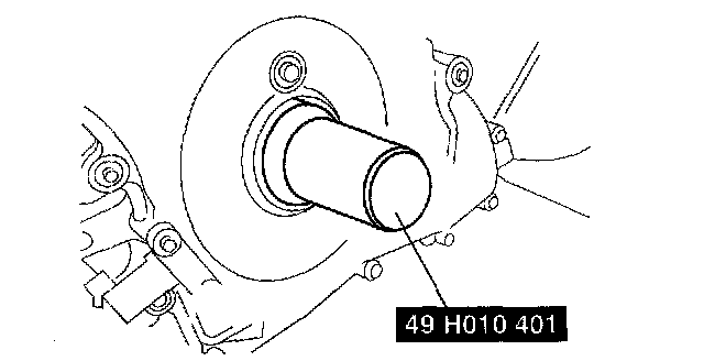
1. Apply clean engine oil to a new front oil seal.
2. Push the front oil seal in the engine front cover by hand.
3. Use the SST to tap in the front oil seal.
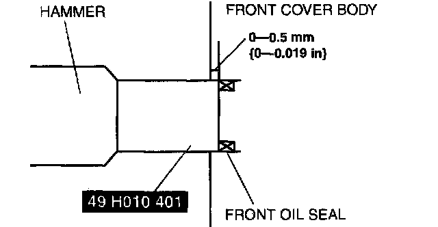
Front oil seal press-in amount 0 - 0.5 mm (0 - 0.019 inch)
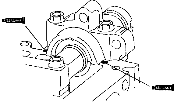
Engine Front Cover Installation Note
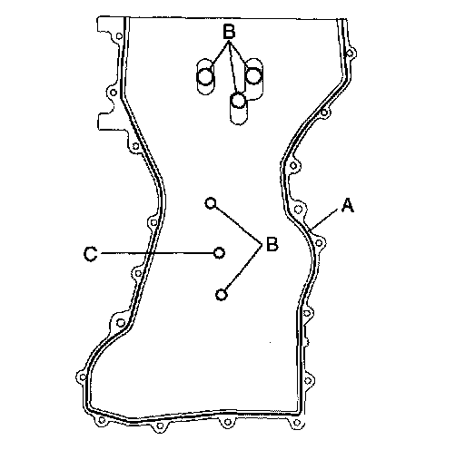
1. Apply silicone sealant to the engine front cover.
Caution:
- Install the engine front cover within 10 min of applying the silicone sealant.
- Silicone sealant is not need in area C as indicated due to an existing seal.
Thickness A: 2.2 - 3.2 mm (0.086 - 0.126 inch)
B: 1.5 - 2.5 mm (0.059 - 0.098 inch)
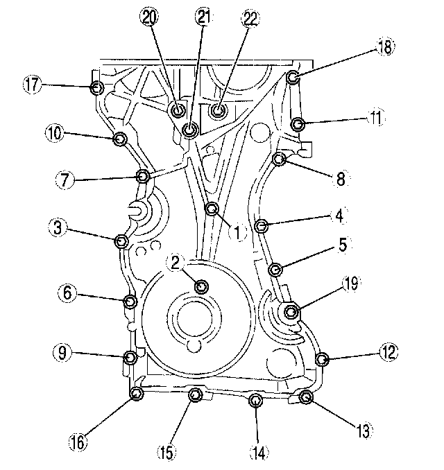
2. Tighten the engine front cover installation bolts in the order shown in the figure.
No.3 Engine Mount Rubber, No.3 Engine Joint Bracket Installation Note

1. Tighten the No.3 engine mount bracket stud bolts.
Tightening torque 7.0 - 13 Nm (71.4 - 132.5 kgf-cm, 62.0 - 115.0 inch lbs.)
2. Temporarily tighten the No.3 engine mount rubber installation bolts.
3. Install the No.3 engine joint bracket and tighten the bolts and nuts in the order shown in the figure.
Crankshaft Pulley Lock Bolt Installation Note
1. Install the SST to the camshaft as shown in the figure.
2. Verify that cylinder No. 1 is at TDC of the compression stroke. (Position crank weight contacts SST.)
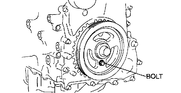
3. To position the crankshaft pulley, temporarily tighten it and, using a suitable bolt (M6 X 1.0 length 25-35 mm (0.99-1.37 inch)), fix the crankshaft pulley to the engine front cover.
4. Install the SSTs to the crankshaft pulley, lock the crankshaft against rotation, and tighten the crankshaft pulley lock bolt using the following two steps.
Tightening procedure
(1) 96 - 104 Nm (9.8 - 10.6 kgf-m, 70.9 - 76.7 ft. lbs.)
(2)87°- 93°
5. Remove the bolt (M6 X 1.0 length 25-35 mm (0.99-1.37 inch)) installed to the crankshaft pulley
6. Remove the SST from the camshaft.
7. Remove the SST installed in the cylinder block lower blind plug hole.
8. Rotate the crankshaft clockwise two turns and inspect the valve timing.
- If not aligned, repeat from Step 1.
9. Install the cylinder block lower blind plug.
Tightening torque 18 - 22 Nm (1.9 - 2.2 kgf-m, 13.3 - 16.2 ft. lbs.)
Cylinder Head Cover Installation Note
1. Apply silicone sealant to the areas shown in the figure.
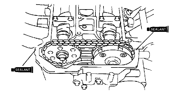
Thickness 5.0 mm (0.196 inch)
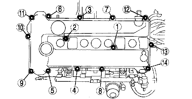
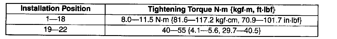
2. Tighten the cylinder head cover bolts in the order shown in the figure.
Tightening torque 8.0 - 10.5 Nm (81.6 - 107.1 kgf-cm, 70.8 - 92.9 inch lbs.)