Boost Air Temperature Sensor Inspection
BOOST AIR TEMPERATURE SENSOR INSPECTION [L3 WITH TC]Resistance Inspection
NOTE: Perform the following inspection only when directed.
1. Disconnect MAP/boost air temperature sensor.
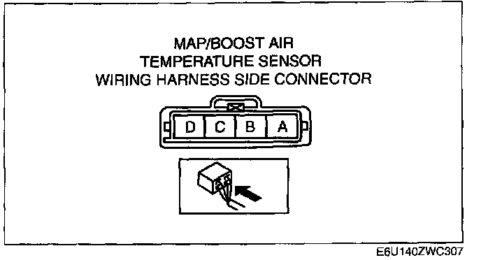
2. Measure the resistance between the MAP/boost air temperature sensor terminals A and B using a tester.
- If not as specified, replace the MAP/boost air temperature sensor. (See INTAKE AIR SYSTEM REMOVAL/INSTALLATION [L3 WITH TC].)
- If the MAP/boost air temperature sensor is normal, but PID are out of specification, perform the "Circuit Open/Short Inspection".
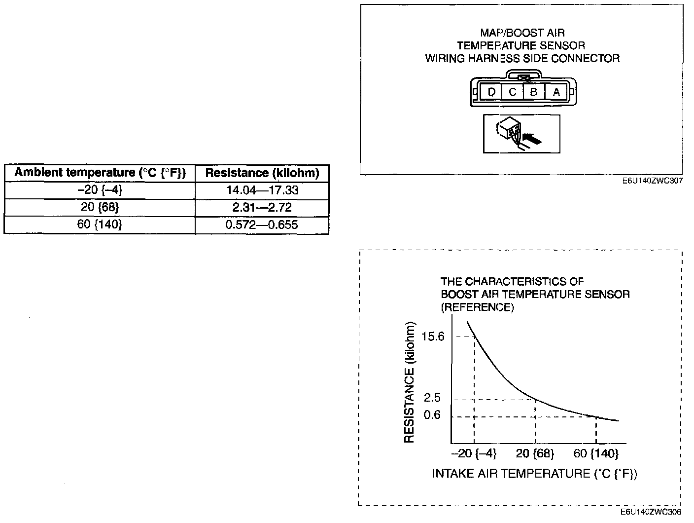
Specification
Circuit Open/Short Inspection
1. Disconnect the PCM connector.
2. Inspect the following wiring harnesses for an open or short circuit. (Continuity check)
Open circuit
- If there is no continuity, there is an open circuit. Repair or replace the wiring harness.
- MAP/boost air temperature sensor terminal A and PCM terminal 2H
- MAP/boost air temperature sensor terminal B and PCM terminal 13
- MAP/boost air temperature sensor terminal C and PCM terminal 2K
Short circuit
- If there is continuity, there is a short circuit. Repair or replace the wiring harness.
- MAP/boost air temperature sensor terminal A and power supply
- MAP/boost air temperature sensor terminal B and power supply
- MAP/boost air temperature sensor terminal B and body ground
- MAP/boost air temperature sensor terminal C and body ground