Control Valve Body Removal/Installation [AW6A-EL]
CONTROL VALVE BODY REMOVAL/INSTALLATION [AW6A-EL]On-Vehicle Removal
Warning:
^ Using compressed air can cause dirt and other particles to fly out, causing injury to the eyes. Wear protective eyeglasses whenever using compressed air.
Caution:
^ Clean the transaxle exterior throughout with a steam cleaner or cleaning solvents before removal.
^ If any old sealant gets into the transaxle during installation of the control valve body cover, trouble may occur in the transaxle case and control valve body cover. Clean with cleaning fluid.
1. Disconnect the negative battery cable.
2. Remove the air cleaner component and air cleaner bracket.
3. Place the heater pipe out of the way.
4. Remove the under cover.
5. Drain the ATE.
6. Drain the engine coolant.
7. Disconnect the lower radiator hose and place the lower radiator hose out of the way.
8. Remove the oil hose, oil pipe and O-ring.
9. Remove the front crossmember.
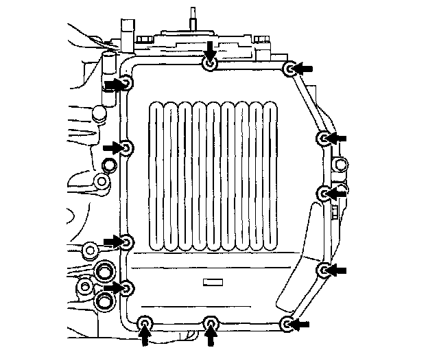
10. Remove the control valve body cover installation bolt.
Caution:
^ Do not damage the fitting surface of the transaxle case and the control valve body cover.
^ Do not deform the control valve body cover.
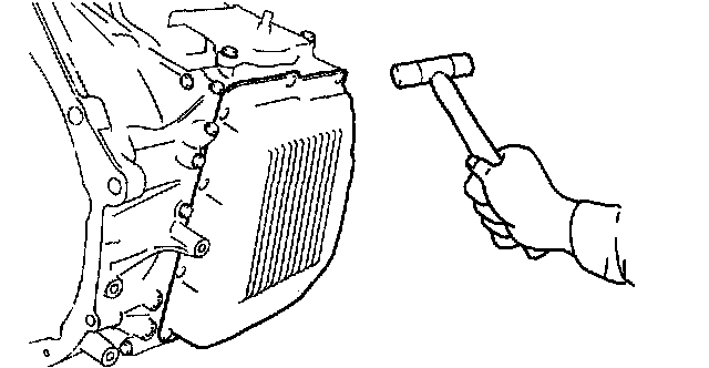
11. Using a plastic hammer, tap the control valve body cover to remove it.
Caution:
^ Be careful not to damage the solenoid valves and connectors.
^ Do not pull the wiring harnesses when removing the connector.
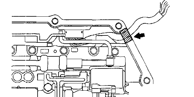
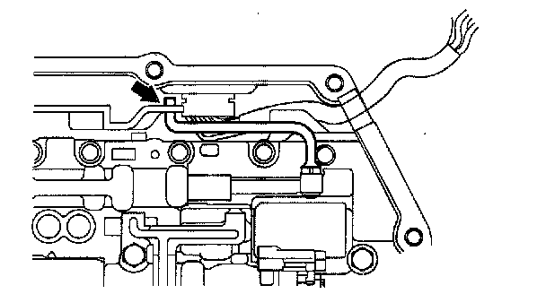
Note:
^ Disconnect the solenoid connector according to the following procedure:
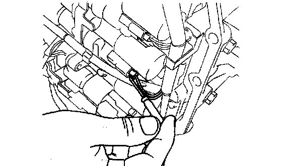
1. Insert a precision screwdriver from the backside into the connector as shown in the figure.
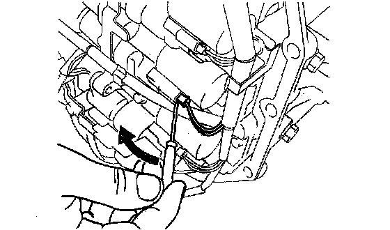
2. Pry the screwdriver in the direction of the arrow and disconnect the connector.
Caution:
^ Do not damage the solenoid valves and connectors with the screwdriver.
^ When disconnecting connectors, grasp the connectors, not the harnesses. Otherwise, the harnesses may be pulled out of the connector causing poor contact.
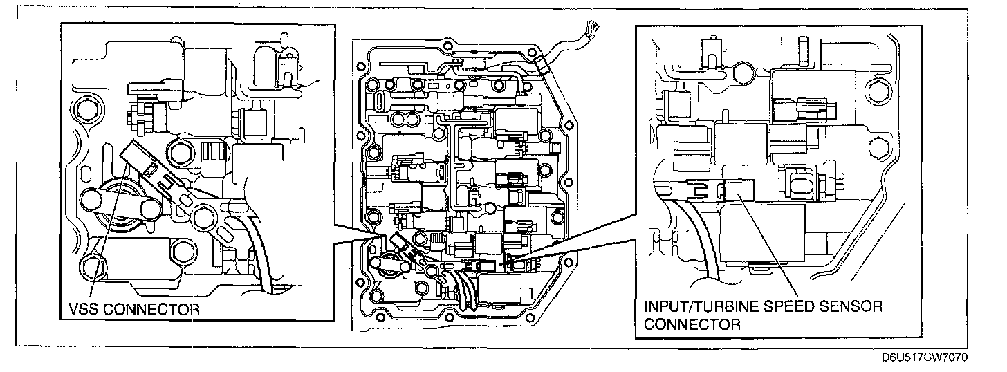
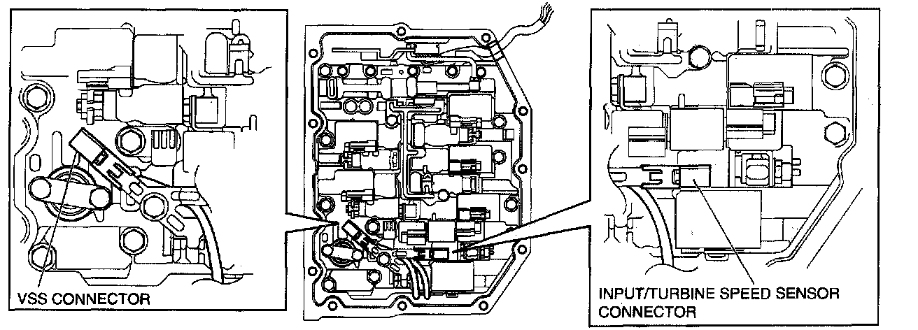
12. Disconnect the solenoid connectors, VSS connector and the input/turbine speed sensor connector.
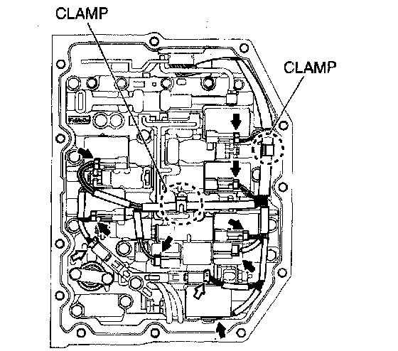
13. Disconnect the coupler component from the clamp.
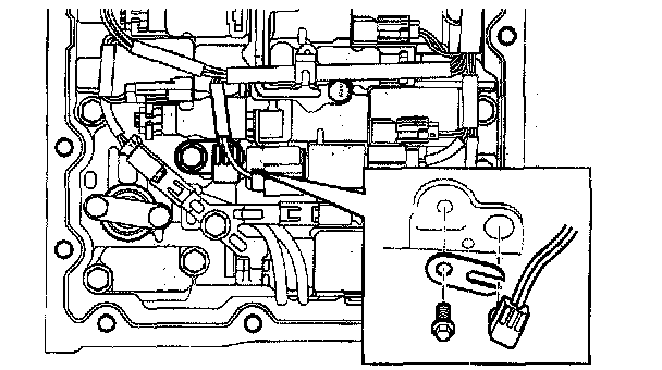
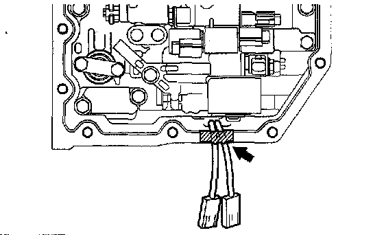
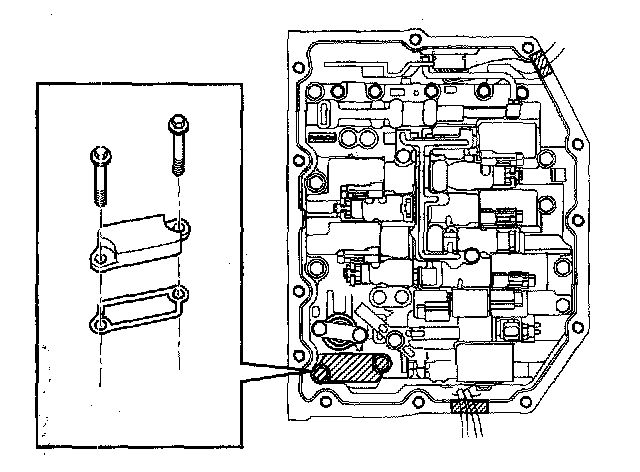
14. Remove the lock plate, and pull out the TFT sensor from the control valve body.
15. Remove the O-ring from the TFT sensor.
Note:
^ Be sure to secure the coupler component with tape so that it will not interfere with the control valve body component.
16. Fix the coupler component with tape to the transaxle case as shown in the figure.
17. Remove the VSS connector and input/turbine speed sensor connector from the solenoid clamp.
Note:
^ Be sure to secure the VSS and input/turbine speed sensor with tape so that they will not interfere with the control valve body component.
18. Fix the VSS wiring harness and input/turbine speed sensor wiring harness with tape to the transaxle case as shown in the figure.
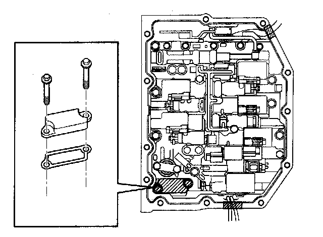
19. Remove the suction cover and the gasket.
Caution:
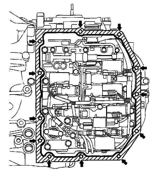
^ Evenly loosen the bolts a little at a time in the order shown in the figure.
20. Remove the control valve body installation bolts.
Caution:
^ Do not drop the control valve body component.
21. Disconnect the manual valve link and remove the control valve body component.
On-Vehicle Installation
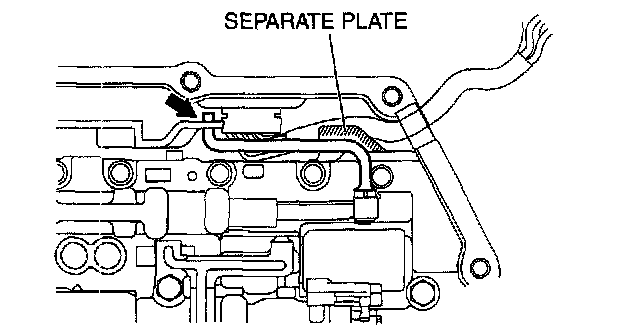
Caution:
^ When installing the control valve body component, do not put the coupler component in the open space of the separate plate in the control valve body component.
^ Do not pinch the coupler component between the separate plate and the control valve body component.
1. Connect the manual valve link and install the control valve body component.
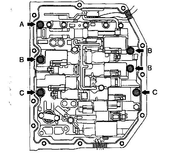
2. Temporarily install the control valve body component with the bolts.
Bolt length (measured from below the head)
A: 31 mm (1.220 inch)
B: 17 mm (0.669 inch)
C: 21 mm (0.827 inch)
Note:
^ Aligning the bolt holes, temporarily tighten the bolt by hand.
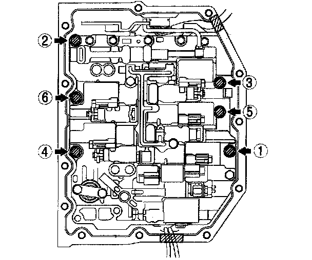
3. Temporarily install the suction cover and a new gasket with the bolts.
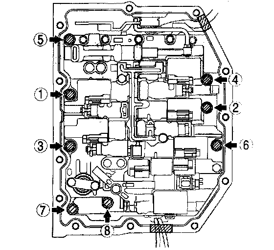
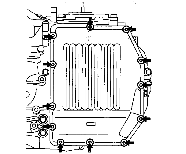
4. Tighten the bolts in the order shown in the figure.
Tightening torque 8 - 12 Nm (82 - 122 kgf-cm, 72 - 105 inch lbs.)
5. Install the connector of the VSS and input/turbine speed sensor to the solenoid clamp.
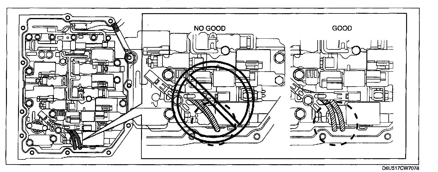
Caution:
^ If the control valve body cover Is installed with the wiring harnesses overlapped, the wiring harnesses may be pinched between the cover and valve body causing the wiring harnesses to be damaged. Therefore, verify that the wiring harnesses are not overlapped when installing the control valve body cover.
6. Apply ATF to a new O-ring and install it on the TFT sensor.
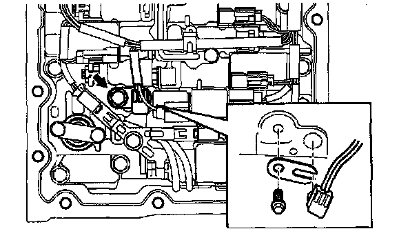
7. Install the TFT sensor with the lock plate and a bolt to the control valve body component as shown in the figure.
Tightening torque 8 - 12 Nm (82 - 122 kgf-cm, 72 - 105 inch lbs.)
8. Connect the solenoid connectors, VSS connector and the input/turbine speed sensor connector.
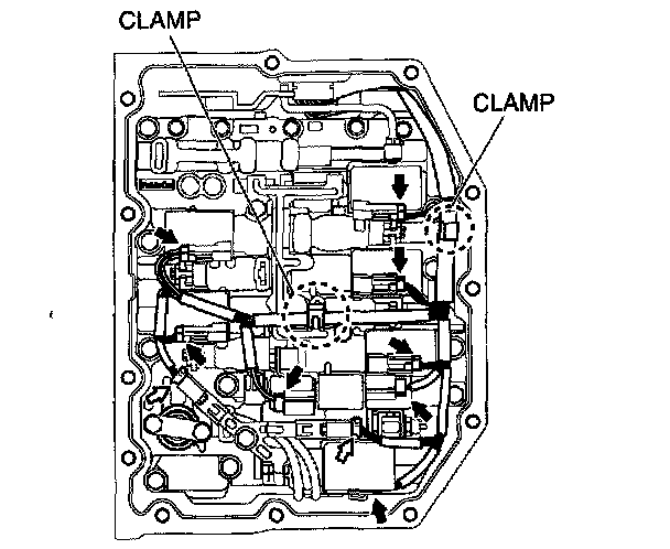
9. Connect the coupler component to the clamps.
Note:
^ Completely remove sealant and oil with white gasoline or similar.
10. Clean sealant and oil off the contact surface of the transaxle case with the control valve body cover and the bolt holes.
Note:
^ Completely remove oil with white gasoline or similar.
11. Clean oil off the contact surface of the new control valve body cover with the transaxle case.
12. Apply sealant to the new control valve body cover as shown in the figure.
Caution:
^ Be careful that the coupler component will not become caught between the control valve body cover and transaxle case.
13. Install the new control valve body cover with new seal bolts.
Tightening torque 9.8 - 15.7 Nm (100 - 160 kgf-cm, 87 - 138 inch lbs.)
14. Apply ATF to a new O-ring and install it on the oil pipe.
15. Install the oil pipe and oil hose.
16. Connect the lower radiator hose.
17. Add the engine coolant.
18. Add ATF to the specified level.
19. Install the front crossmember.
20. Install the under cover.
21. Install the air cleaner component and air cleaner bracket.
22. Connect the negative battery cable.
23. Perform the mechanical system test.