Propeller Shaft Disassembly/Assembly
PROPELLER SHAFT DISASSEMBLY/ASSEMBLY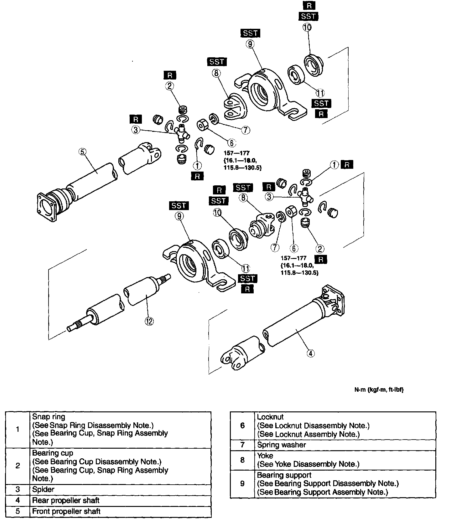
Caution:
^ If using a vise, always secure the component using an aluminum plate to prevent component damage.
1. Disassemble in the order indicated in the table.
2. Assemble in the reverse order of disassembly.
Note:
^ Rear Differential side universal joint can not be disassembled.
Snap Ring Disassembly Note
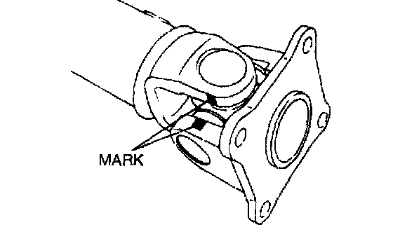
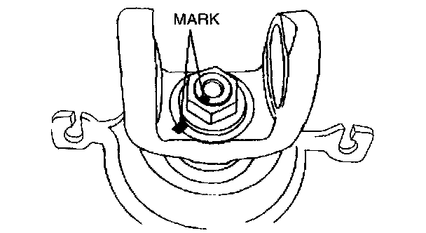
1. Place an alignment mark on the yoke and front propeller shaft, or on the yoke and rear propeller shaft.
2. Secure the propeller shaft to the vise.

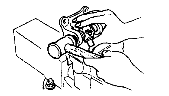
3. Remove the snap ring using a flathead screwdriver.
Bearing Cup Disassembly Note
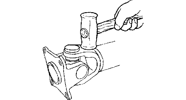
1. Using a copper hammer, raise the propeller shaft bearing cup and remove.
2. Remove the bearing cup on the opposite side by following the same procedure.
3. Remove the front propeller shaft from the yoke.
4. Secure the yoke on a vise, and remove the bearing cup by following Steps 1 and 2.
Locknut Disassembly Note
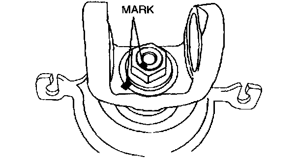
1. Place alignment marks on the yoke and center propeller shaft.
2. Secure the yoke on the vise.
3. Remove the locknut and washer.
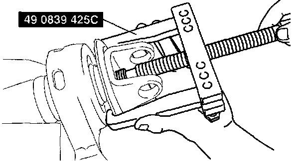
4. Remove the yoke using the SSTs.
Yoke Disassembly Note
Front:
Rear:
1. Remove the yoke using the SST.
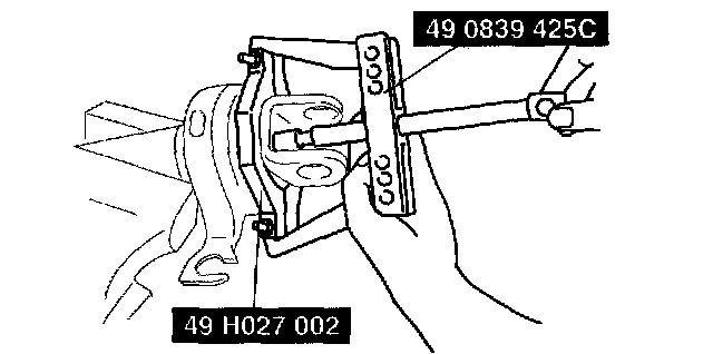
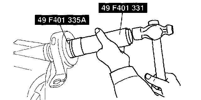
Bearing Support Disassembly Note
1. Remove the bearing support using the SSTs.
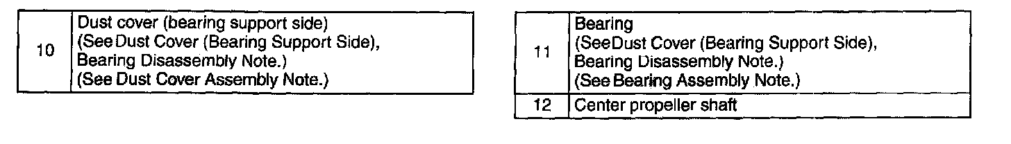
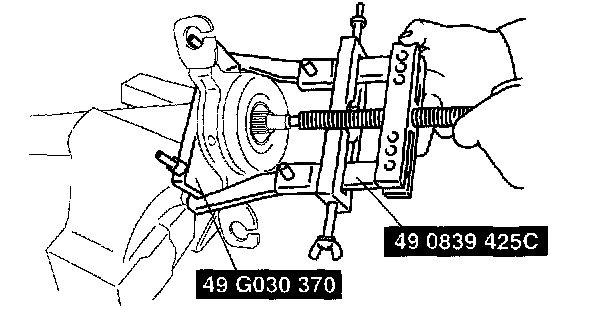
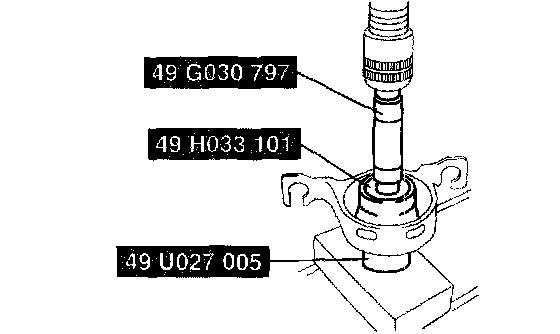
Dust Cover (Bearing Support Side), Bearing Disassembly Note

1. Remove the bearing and dust cover (bearing support side) from the bearing support using the SSTs and a press.
Bearing Assembly Note
1. Assemble the bearing to the bearing support using the SSTs.
Dust Cover Assembly Note
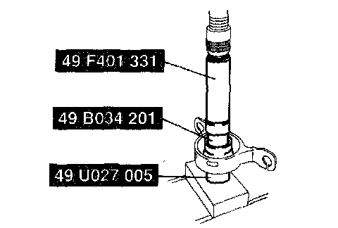
1. Assemble the dust cover to the bearing support using the SSTs and a press.
Bearing Support Assembly Note
Front:
Rear:
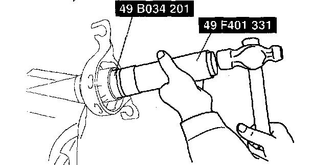
1. Assemble the bearing support to the propeller shaft using the SSTs.
Locknut Assembly Note
1. Align the alignment marks on the propeller shaft and yoke, and assemble.
Tightening Torque 157 - 177 Nm (16.1 - 18.0 kgf-m, 115.8 - 130.5 ft. lbs.)
Bearing Cup, Snap Ring Assembly Note
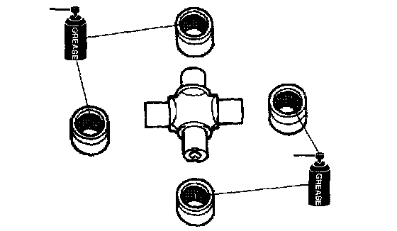
1. Set the new spider on the yoke and assemble a new bearing cup until the snap ring groove can be seen.
2. Assemble the opposite side by following the same procedure.
3. Insert the bearing cup and adjust it so that the snap ring groove has the largest width and both sides have the same groove width.
Caution:
^ Use snap rings with the same thickness on both sides.
4. Measure the bearing cup groove width and install a new snap ring of the proper size.
Snap ring thickness 1.45 mm (0.0571 inch), 1.48 mm (0.0583 inch), 1.51 mm 10.0594 inch), 1.54 mm (0.0606 inch), 1.57 mm (0.0618 inch), 1.60 mm (0.0630 inch), 1.63 mm (0.0642 inch)
5. Lightly tap the yoke using a copper hammer and press the snap ring to the yoke.
6. Verify that the spider has no excessive play.
7. Align the propeller shaft and yoke with the alignment mark and install.
8. Assemble the bearing cup and snap ring by following Steps 1-6.
9. Lightly tap the universal joint outer edge using a plastic hammer to adjust the component to the proper position.