Component Tests and General Diagnostics
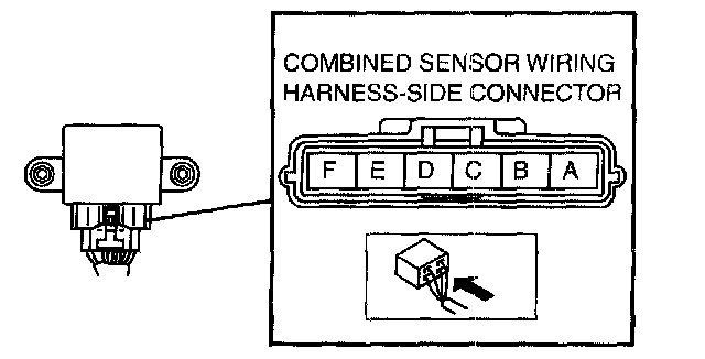
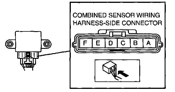
COMBINED SENSOR INSPECTIONCaution:
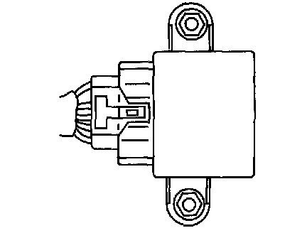
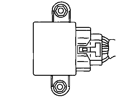
^ The internal parts of the combined sensor could be damaged if dropped. Be careful not to drop the combined sensor. Replace the combined sensor if it is subjected to an impact. Also, do not use an impact wrench or other similar air tools when removing/installing the sensor.
Lateral-G Sensor Inspection
1. Connect the connector.
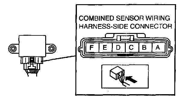
2. Turn ignition switch on, verify the voltage between terminals B and ground terminal E under the following conditions.
^ If not within the specification, replace the combined sensor.
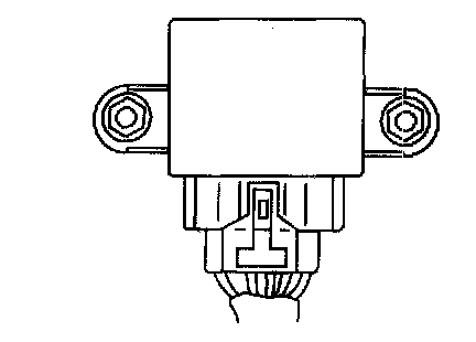
1) Horizontal
Voltage 2.4 - 2.6 Volts
2) Facing up (inclined 90° from horizontal)
Voltage 3.3 - 3.7 Volts
3) Facing down (declined 90° from horizontal)
Voltage 1.3 - 1.7 Volts
Yaw Late Sensor Inspection
1. Connect the connector.
2. Turn ignition switch on, verify the voltage between terminals D and ground terminal E under the following conditions.
1) Measure combined sensor voltage under static condition.
Voltage 2.3 - 2.7 Volts
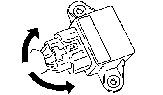
2) Measure voltage at output terminal D and ground terminal E when the combined sensor is rotated left and right.
Caution:
^ Be careful when turning the combined sensor rotation position while it is in a reversed state because the rotation direction and voltage will be reversed.
Voltage Right rotation: fluctuation between 2.5 - 4.62 Volts
Left rotation: fluctuation between 2.5 - 0.33 Volts
Forward-G Sensor Inspection
1. Connect the connector.
2. Turn ignition switch on, verify the voltage between terminals A and ground terminal E under the following conditions.
1) Horizontal
Voltage 2.2 - 2.8 Volts
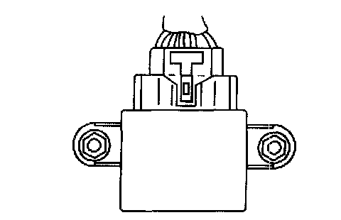
2) Acceleration (inclined 90° from horizontal)
Voltage 3.1 - 3.9 Volts
3) Deceleration (decline 90° from horizontal)
Voltage 1.2 - 1.8 Volts