Removal/Installation
MASTER CYLINDER REMOVAL/INSTALLATION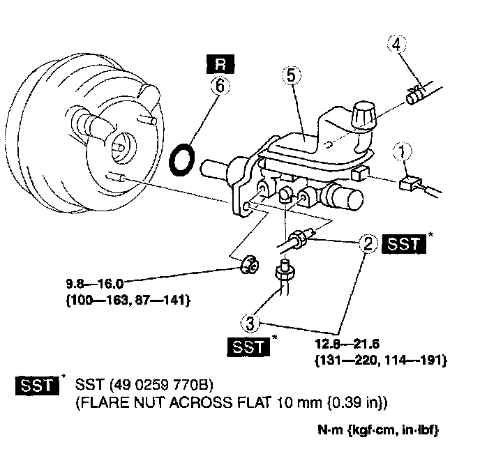
1. Remove the battery and battery tray.
2. Remove in the order indicated in the table.
3. Install in the reverse order of removal.
Master Cylinder Installation Note
Caution:
^ If the master cylinder is installed at a slanted angle to the power brake unit, the master cylinder piston may jam against the push rod retainer of the power brake unit, causing improper air bleeding, brake drag or other malfunctions. Be sure to install the master cylinder at a level, perpendicular angle to the power brake unit.
^ Always install the gasket of the power brake unit push rod before performing measurement inspections or adjustments.
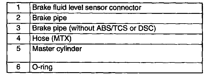
1. Install the SST to the power brake unit as shown, and tighten within the specified torque.
Tightening torque 9.8 - 16.0 Nm (100 - 163 kgf-cm, 87 - 141 inch lbs.)
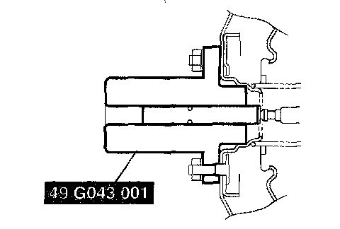
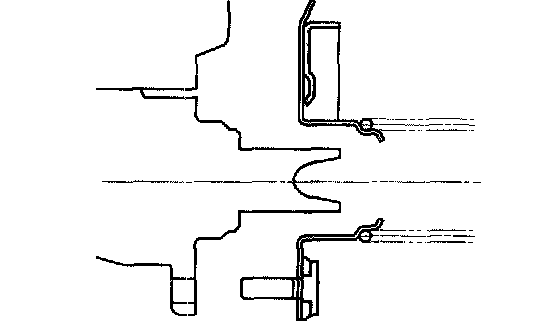
2. Using a vacuum gauge, create a vacuum pressure of 66.7 kPa (500 mmHg, 19.7 in-Hg) in the power brake unit.
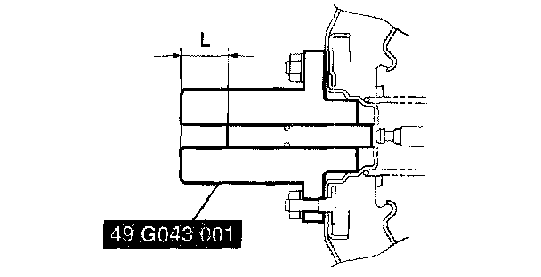
3. Using calipers, measure dimension Liters as shown.
Specification 25.9 - 26.1 mm (1.020 - 1.027 inch)
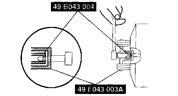
4. If dimension Liters is not within the specification as shown, remove SST (49 G043 001) and use SST (49 B043 004) to adjust the length of the push rod while using SST (49 E043 003A) to keep the push rod from rotating.
5. Remove the SSTs, replace SST (49 G043 001) and measure dimension Liters again.
6. Install the master cylinder to the power brake unit.
Caution:
^ If, after installing the master cylinder, air does not bleed properly from the brake lines even after performing air bleeding, brake drag occurs or other characteristics are present, it is possible that the master cylinder piston is jammed against the power brake unit. If air cannot be bled properly, brake drag exists or other malfunctions occur, remove the master cylinder and reinstall properly.