Fuel Pump Unit Removal and Installation
FUEL PUMP UNIT REMOVAL/INSTALLATIONWARNING:
- Fuel line spills and leakage are dangerous. Fuel can ignite and cause serious injuries or death and damage. Fuel can also irritate skin and eyes. To prevent this, always complete the "Fuel Line Safety Procedure".
- Fuel line spills and leakage are dangerous. Fuel can ignite and cause serious injuries or death and damage. Fuel can also irritate skin and eyes. To prevent this, before performing the fuel pump unit removal/installation, always complete the "Fuel Leak Inspection After Fuel Pump Unit Installation".
- A person charged with static electricity could cause a fire or explosion, resulting in death or serious injury. Before draining fuel, make sure to discharge static electricity by touching the vehicle body.
CAUTION:
- Because the fuel tank is constructed such that the fuel level is higher than the installation surface of the fuel pump, fuel leakage could occur. If the fuel gauge indicates a fuel level of half or more, perform the following Steps 1-6 to drain the fuel.
- Disconnecting/connecting the quick release connector without cleaning it may possibly cause damage to the fuel pipe and quick release connector. Always clean the quick release connector joint area before disconnecting/connecting using a cloth or soft brush, and make sure that it is free of foreign material.
- To prevent the SST from coming off The fuel pump cap while performing the work, always perform the removal/installation procedure with 2 people. One person presses the SST against cap from directly above, while the other person rotates the SST.
1. Complete the "BEFORE REPAIR PROCEDURE".
2. Remove the plug hole plate.
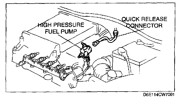
3. Disconnect the quick release connector connected to the high pressure fuel pump.
4. Connect a long hose to the disconnected quick release connector and drain the fuel into a container used for collecting gasoline.
5. Start the fuel pump using the following procedure.
Using WDS or equivalent
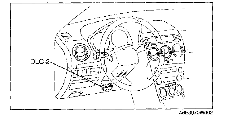
1. Connect the WDS or equivalent to the DLC-2.
2. Using the simulation function "FP", start the fuel pump.
Without using WDS or equivalent
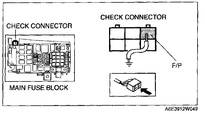
1. Short the check connector terminal F/P to body GND using a jumper wire.
2. Turn the ignition switch to ON position to operate the fuel pump.
CAUTION: The fuel pump could be damaged if it is operated (fuel pump idling) while there is no fuel in the fuel tank. Verify the amount of fuel being discharged from the hose and stop operation of the fuel pump when essentially no fuel is being discharged.
NOTE: If the fuel tank is full, drain approx. 40 L {10.6 US gal, 8.8 Imp gal} of fuel until the fuel gauge indicates approx. 3/8 of a tank.

6. When essentially no fuel is being discharged, stop the fuel pump.
Using WDS or equivalent
1. Using the simulation function "FP", stop the fuel pump.
Without using WDS or equivalent
1. Turn the ignition switch to LOCK position to stop the fuel pump.
2. Disconnect the jumper wire from the check connector.
7. Disconnect the negative battery cable.
8. Complete the following in order to the work area.
1. Loosen the bolt of the fuel tank strap.
2. Lower the fuel tank to a position where the SST can be attached from the service hole cover.
9. Remove the rear seat cushion.
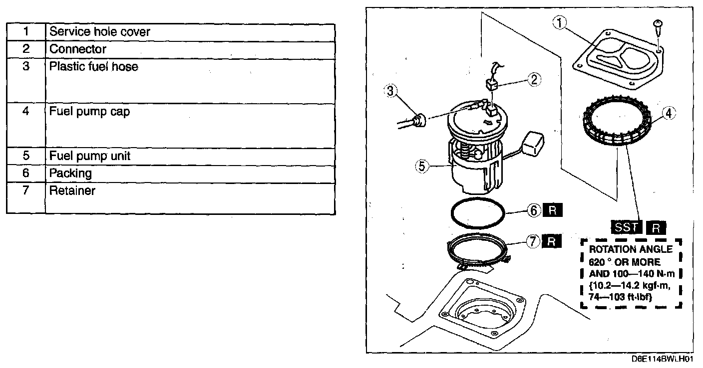
10. Remove in the order indicated in the table.
11. Install in the reverse order of removal.
12. Complete the "AFTER REPAIR PROCEDURE".
Plastic Fuel Hose Removal Note
CAUTION: The quick release connector may be damaged if the tab is bent excessively. Do not expand the tab over the stopper.
1. Disconnect the quick release connector.
2. Cover the disconnected quick release connector and fuel pipe with vinyl sheets or the like to prevent them from being scratched or contaminated with foreign material.
Fuel Pump Cap Removal Note
NOTE: Do not remove the fuel tank strap.
1. Loosen the fuel tank strap installation bolts and lower the fuel tank so that the SST can be set.
CAUTION: The cap could be damaged if the SST is used with any play between the cap and the SST. Securely attach the SST so that there is no gap between the SST tabs and the side of the cap.
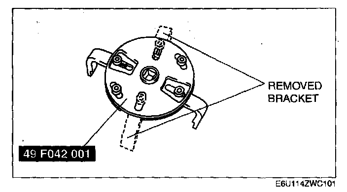
2. Remove the fuel pump cap using the SST with two of the four brackets removed.
Fuel Pump Cap Installation Note
WARNING: Make sure there is no foreign material on each of the parts. If there is foreign material on the parts, the fuel pump unit cannot be assembled correctly, which could result in fuel leakage.
NOTE: The fuel pump unit will rotate and cannot be secured in the specified position if there is any gasoline on the gasket. Thoroughly wipe away all gasoline from the gasket.
1. Replace the packing, fuel pump cap and the retainer with new parts.
CAUTION: New parts can deform depending on the temperature. If the parts deform, the fuel pump unit cannot be assembled correctly, which could result in fuel leakage. Therefore, keep new parts at room temperature for the specified period of time to stabilize the shape.
2. Leave new parts inside for the following period of time:
Stand-by time: 12 h or more
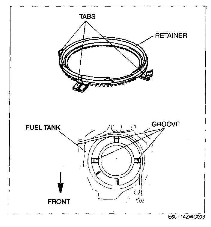
3. Install a new retainer to the fuel tank.
1. Align the retainer tabs (3 locations) with the fuel tank grooves.
2. Verify that the tabs are inserted into the grooves and the retainer is installed correctly.
3. Verify the retainer is not damaged.
4. Install a new packing to the fuel tank.
1. Verify the packing groove is clean and free of foreign material.
2. Install the packing to the fuel tank so that it is inserted into the fuel tank grooves.
CAUTION: Install the fuel pump unit to the fuel tank being careful not to bend the fuel sender unit arm. If the arm is bent, the fuel sender unit will not operate correctly.
5. Install the fuel pump unit to the fuel tank.
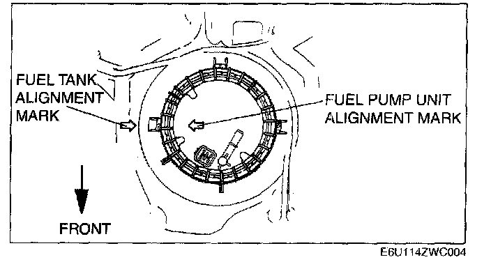
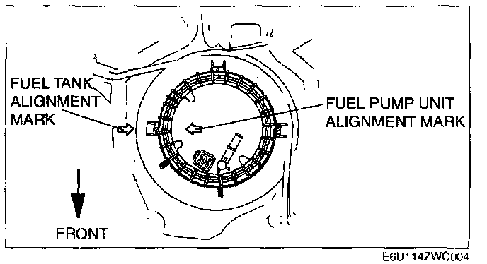
1. Align the fuel tank and fuel pump unit alignment marks as shown in the figure.
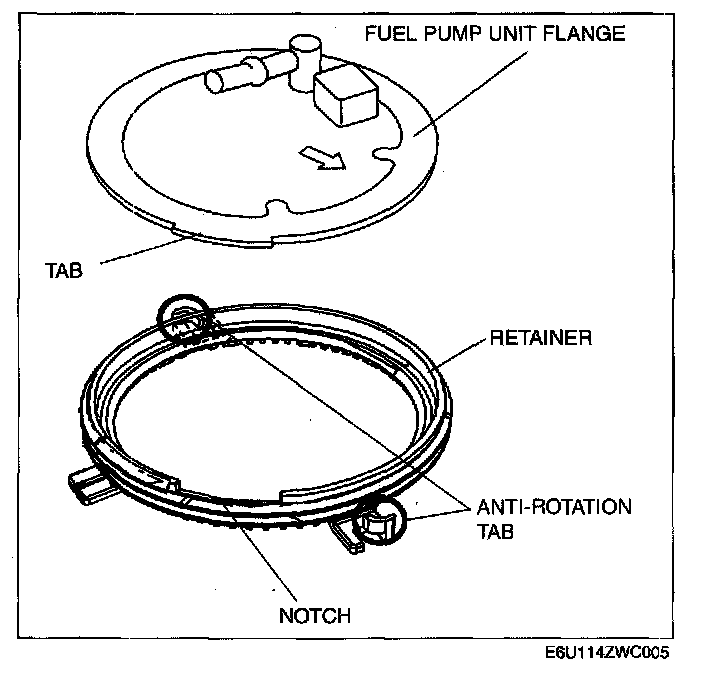
2. Verify the tab on the fuel pump unit flange with the notch on the retainer.
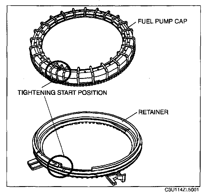
6. Set on a new fuel pump cap.
1. Apply downward force (push down) on the center of the fuel pump unit flange.
NOTE:
- Align the fuel pump cap with the tightening start position of the retainer and tighten the fuel pump cap with the start position as 0 degrees.
- The fuel pump cap tightening start position is the position where the spaces between the ribs become narrow. The retainer tightening start position is the notch position.
2. Align the tightening start position on the fuel pump cap and the tightening start point of the retainer.
WARNING:
- No grease or lubrication allowed on parts during installation. Parts could slide or they cannot be tightened to the specified torque. As a result, fuel leakage could occur.
- When tightening the fuel pump cap, be careful that the fuel tank and fuel pump unit alignment marks have not deviated. If there is deviation, the fuel pump unit cannot be installed correctly, which could result in fuel leakage.
7. Tighten the fuel pump cap.
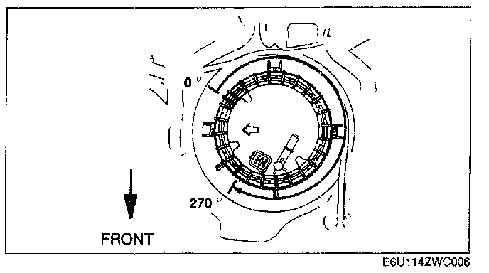
1. Tighten the fuel pump cap by hand to the specified angle or more until the flange is fixed.
Fuel pump cap rotation angle: 270 degrees or more
2. Verify that the fuel pump cap is tightened correctly.
1. The gap between the bottom of the fuel pump cap and the tank surface is even all around.
- If the fuel pump cap is not tightened uniformly, loosen it by hand and reinstall it,
CAUTION: The cap could be damaged if the SST is used with any play between the cap and the SST. Securely attach the SST so that there is no gap between the SST tabs and the side of the cap.
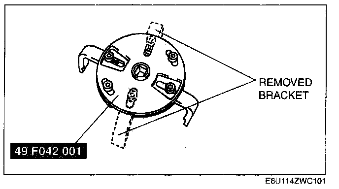
3. Install the SST with two of the four brackets removed.
NOTE: The fuel pump cap rotation angle is the angle from the 0 degrees position. The angle tightened to using the SST includes the angle tightened by hand.
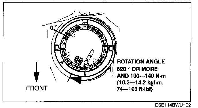
4. Tighten the fuel pump cap to the specified torque and to the specified angle or more.
- If the specified tightening torque and rotation angle cannot be obtained, replace the fuel tank.
Fuel pump cap rotation angle: 620 degrees or more
Fuel pump cap tightening torque: 100-140 N.m {10.2-14.2 kgf.m, 74-103 ft.lbf}
5. Verify that the fuel pump cap is tightened correctly.
1. The gap between the top of the fuel pump unit flange and the fuel pump cap is even all around.
- If it is not tightened uniformly, re-install it using the following procedure.
2. The gap between the fuel pump unit and fuel tank is even all around.
- If it is not tightened uniformly, re-install it using the following procedure.
3. Verify that the fuel tank and fuel pump unit alignment marks are aligned.
- If they are not aligned, re-install it using the following procedure.
CAUTION: The cap could be damaged if the SST is used with any play between the cap and the SST. Securely attach the SST so that there is no gap between the SST tabs and the side of the cap.
8. Install the SST with two of the four brackets removed.
9. Remove the fuel pump cap, fuel pump unit, packing, and retainer.

10. Verify that the retainer is not damaged.
- If both of the retainer anti-rotation tabs are broken, replace it with new one.
11. Return to Step 2 and re-install.
12. Tighten the fuel tank strap bolts.
Tightening torque: 43.1-60.8 N.m {4.40-6.19 kgf.m, 31.8-44.8 ft.lbf}