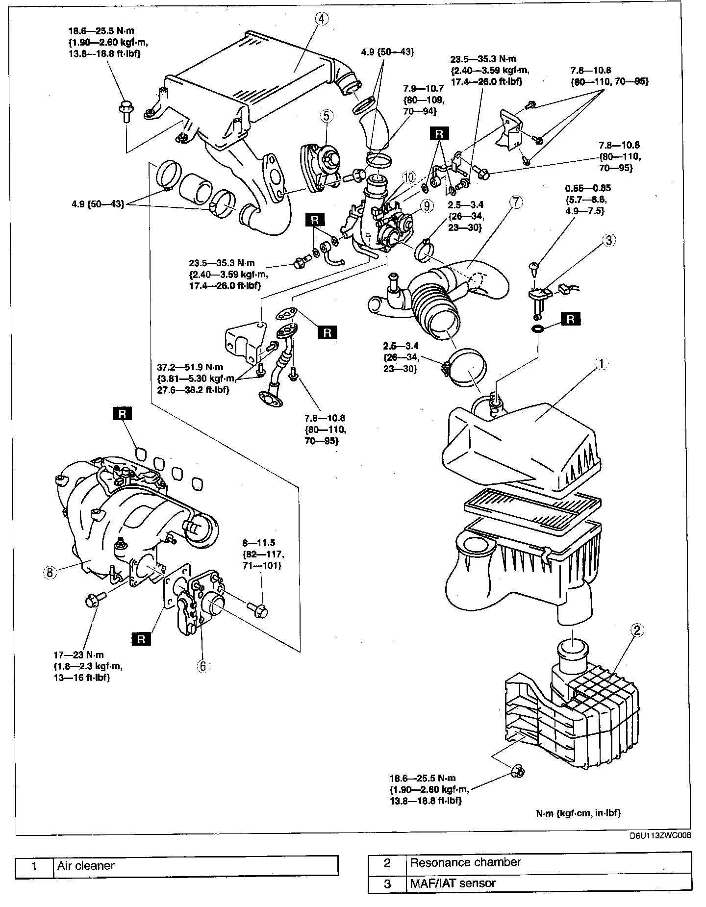
Intake-Air System Removal/Installation
INTAKE AIR SYSTEM REMOVAL/INSTALLATIONWARNING:
- A hot engine and intake air system can cause severe burns. Turn off the engine and wait until they are cool before removing the intake air system.
- Fuel vapor is hazardous. It can easily ignite, causing serious injury and damage. Always keep sparks and flames away from fuel.
- Fuel line spills and leakage are dangerous. Fuel can ignite and cause serious injuries or death and damage. Fuel can also irritate skin and eyes. To prevent this, always complete the "Fuel Line Safety Procedure".
1. Disconnect the negative battery cable.
2. Remove the charge air cooler cover.
3. Remove the battery and battery tray.
4. Remove in the order indicated in the table.
5. Install in the reverse order of removal.
6. Complete the "AFTER REPAIR PROCEDURE".
Resonance Chamber Removal Note
1. Remove the front mudguard (LH) before removing the resonance chamber.
Charge Air Cooler Removal Note
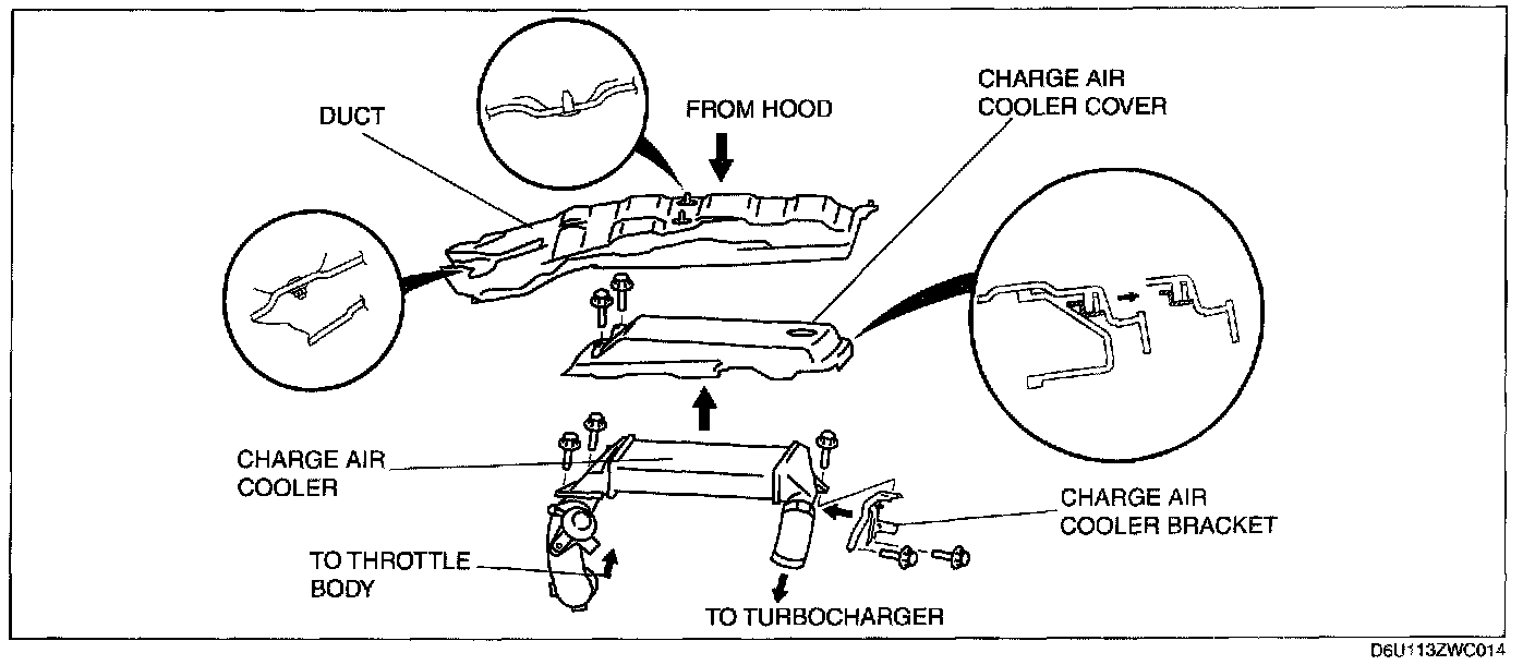
1. Remove the duct.
2. Remove the charge air cooler cover.
3. Remove the charge air cooler.
4. Remove the charge air cooler bracket.
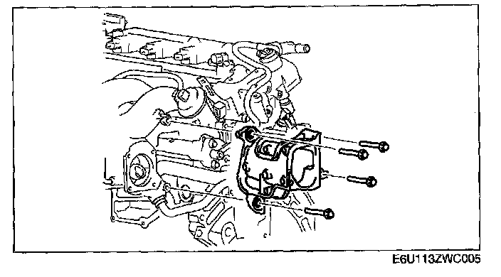
Throttle Body Removal Note
1. Drain the engine coolant before removing the water hose.
2. Remove the throttle body.
Air Hose Removal Note
1. Disconnect the EGR valve connector.
2. Remove the air hose.
Intake Manifold Removal Note
1. Remove the high pressure fuel pump bracket and the EGR pipe bracket.
2. Remove the fuel delivery pipe cover.
3. Remove the oil level gauge pipe.
4. Remove the drive belt.
5. Set the power steering pump out of the way.
6. Remove the vacuum hose.
7. Remove the intake manifold.
Turbocharger Removal Note
1. Remove the TWC.
2. Disconnect the rear HO2S connector.
3. Remove the front pipe.
CAUTION: When removing the cowl, a part or tool may hit the edge of the windshield and could damage it. Protect the windshield by covering it with a clean rag to prevent damage to the windshield.
4. Remove the cowl and the insulator under the cowl.
5. Remove the insulator (Exhaust manifold upper side).
6. Set the generator out of the way
7. Remove the insulator (Exhaust manifold lower side)
8. Disconnect the front HO2S connector.
9. Remove the insulator (WU-TWC top side).
10. Remove the vacuum hose (Brake master back side).
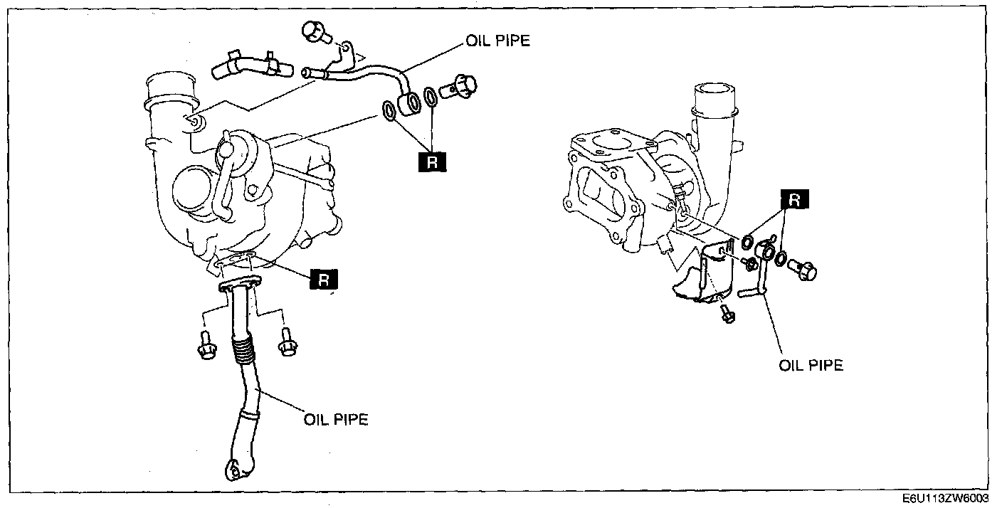
11. Remove the oil pipes.
12. Remove the front HO2S.
13. Remove the WU-TWC
14. Remove the turbocharger.
Turbocharger Installation Not
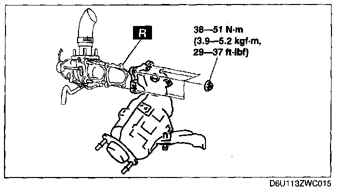
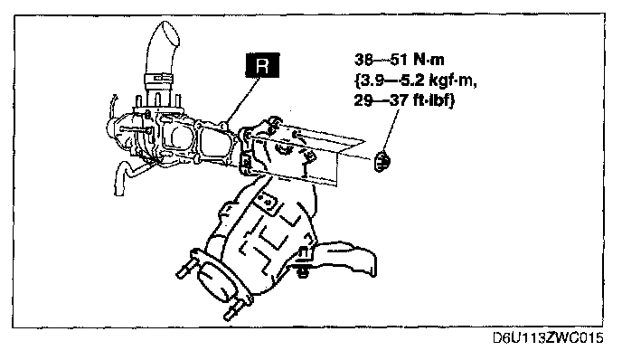
1. Install the turbocharger.
Tightening torque: 38-51 N.m {3.9-5.2 kgf.m, 29-37 ft.lbf}
2. Install the WU-TWC.
3. Install the front HO2S
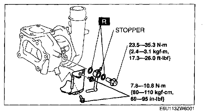
4. Tight the oil pipe installation bolt while the stopper of the oil pipe is faced to the turbocharger.
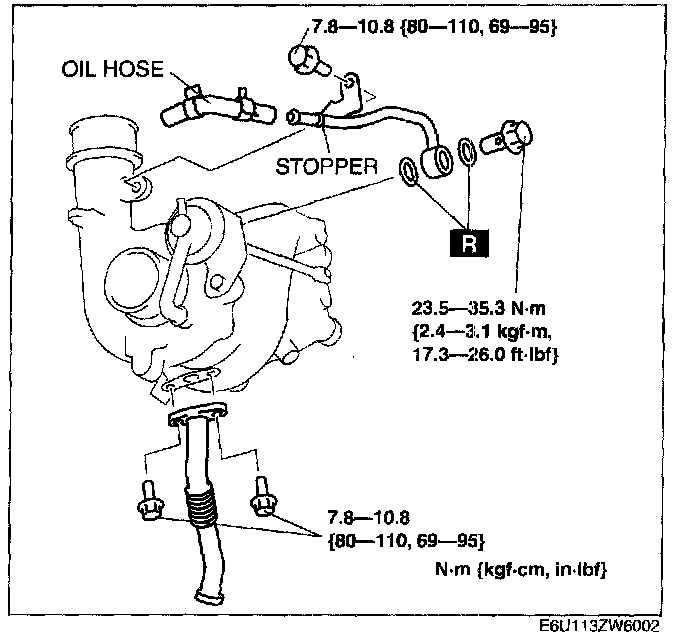
5. Install the oil pipes and, insert the oil hose until it reaches the stopper.
Wastegate Control Solenoid Valve Installation Note
1. Install the wastegate control solenoid valve.
Tightening torque: 7.8-10.8 N.m {80-110 kgf.cm, 70-95 in.lbf}
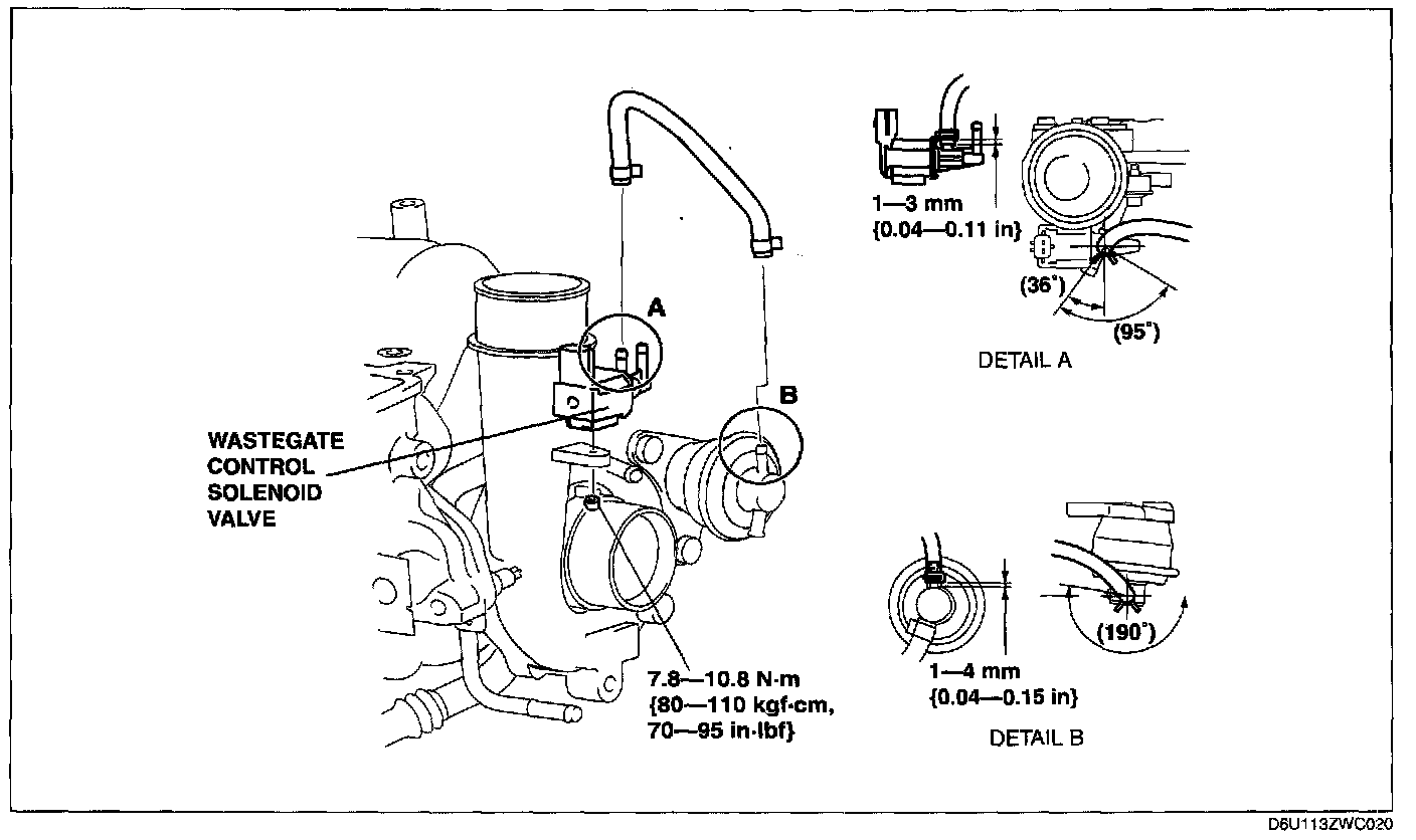
2. Install the hose as shown in the figure.
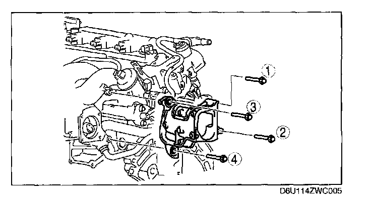
Intake Manifold Installation Note
1. Install the intake manifold.
Tightening torque: 17-23 N.m {1.8-2.3 kgf.m, 13-16ft.lbf}
2. Install the vacuum hose.
3. Install the drive belt.
4. Install the oil level gauge pipe. (See OIL PAN REMOVAL/INSTALLATION.)
5. Install the fuel delivery pipe cover in the order in the figure.
Tightening torque: 17-23 N.m {1.8-2.3 kgf.m, 13-16 ft.lbf}
6. Install the high pressure fuel pump bracket and the EGR pipe bracket.
Charge Air Cooler Installation Note:
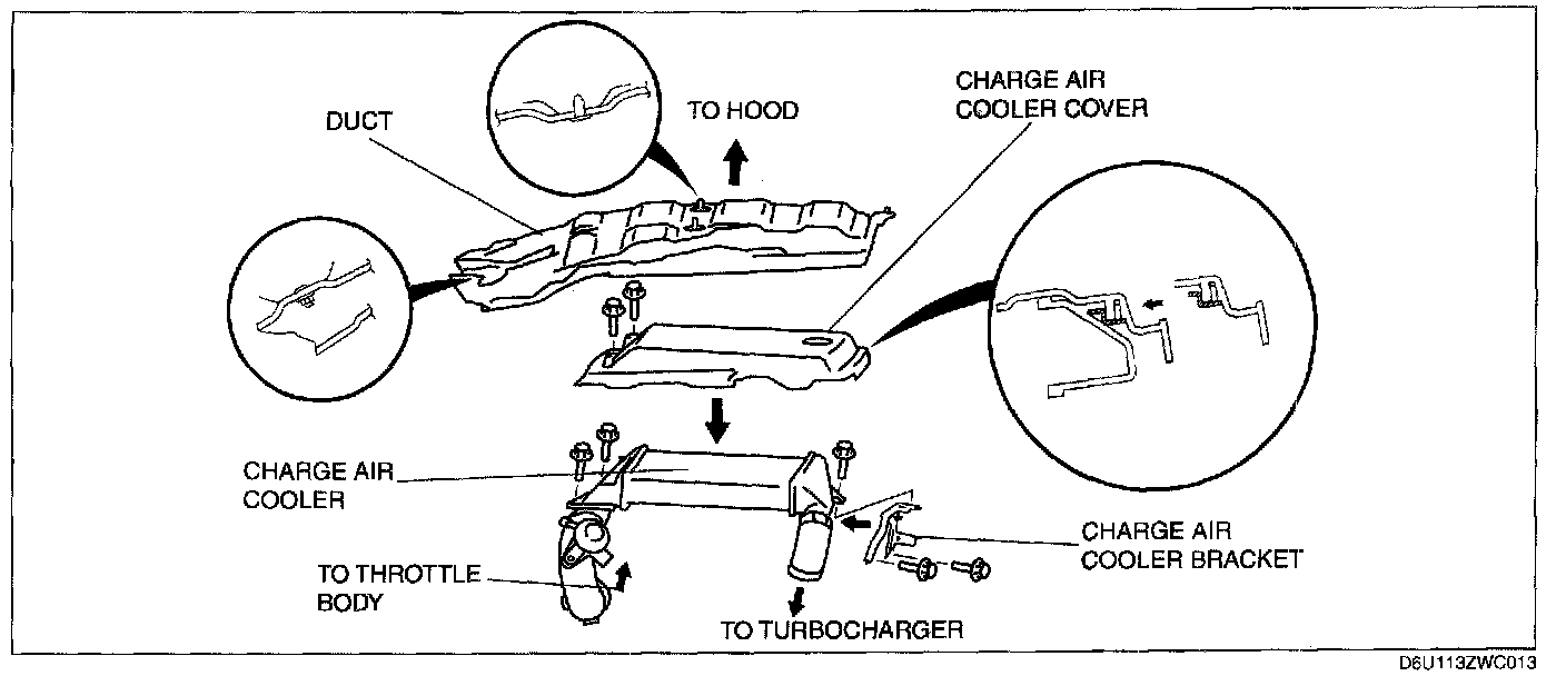
Charge air cooler installation Note
1. Install the charge air cooler bracket.
Tightening torque: 42-48 N.m {4.3-2.8 kgf.m, 31-35 ft.lbf}
2. Install the charge air cooler.
Tightening torque: 18.6-25.5 N.m {1.90-2.60 kgf.m, 13.8-18.8 ft.lbf}
3. install the charge air cooler cover.
CAUTION: When installing the charge air cooler cover, be careful not to damage the charge air cooler cover clips.
Tightening torque: 7.9-10.7 N.m {81-109 kgf.cm, 70-94 in.lbf}
4. install the duct.
Throttle Body Installation Note
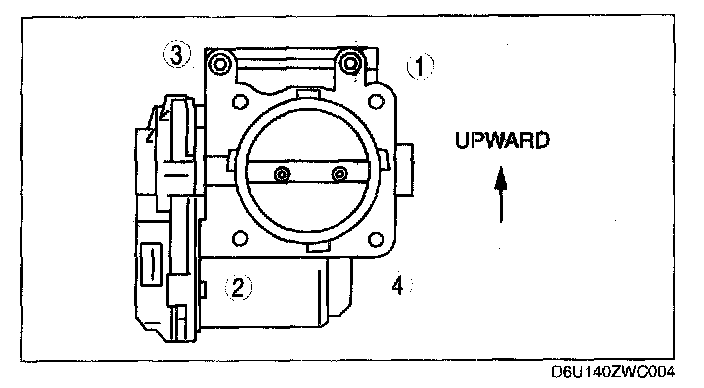
1. Tighten the throttle body installation bolts in the order shown in the figure.
Tightening torque: 8-11.5 N.m {82-117 kgf.cm, 71-101 in.lbf}
Air Cleaner Case Installation Note
CAUTION: Before assembling the air cleaner, verify that the rubber mounts have not fallen off from the air cleaner bracket (3 locations).
- Always install the air cleaner case using the following procedure.
NOTE: When inserting the rubber mounts into the air cleaner case, soapy water can be applied.
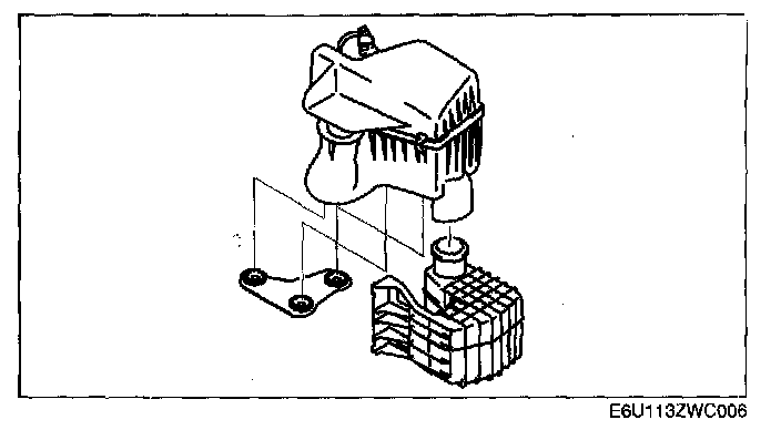
1. Verify that the rubber mounts are set in the air cleaner bracket (3 locations).
2. Install the projections on the frame side (2 locations).
3. Verify that the projections on the frame side are installed securely.
4. Install the projection on the engine side (remaining location).
5. Verify that the projection on the engine side installed securely.